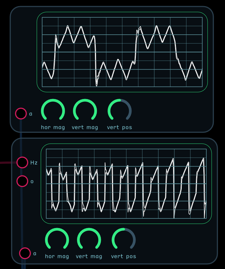
I made the most basic patch (attached below) and I hear a small (“thumpy”) click, even when there is no audio. I can see that removing the amp input on the oscillator removes the click… but I don’t understand why…
I need to have an amp value for the oscillator to work right?
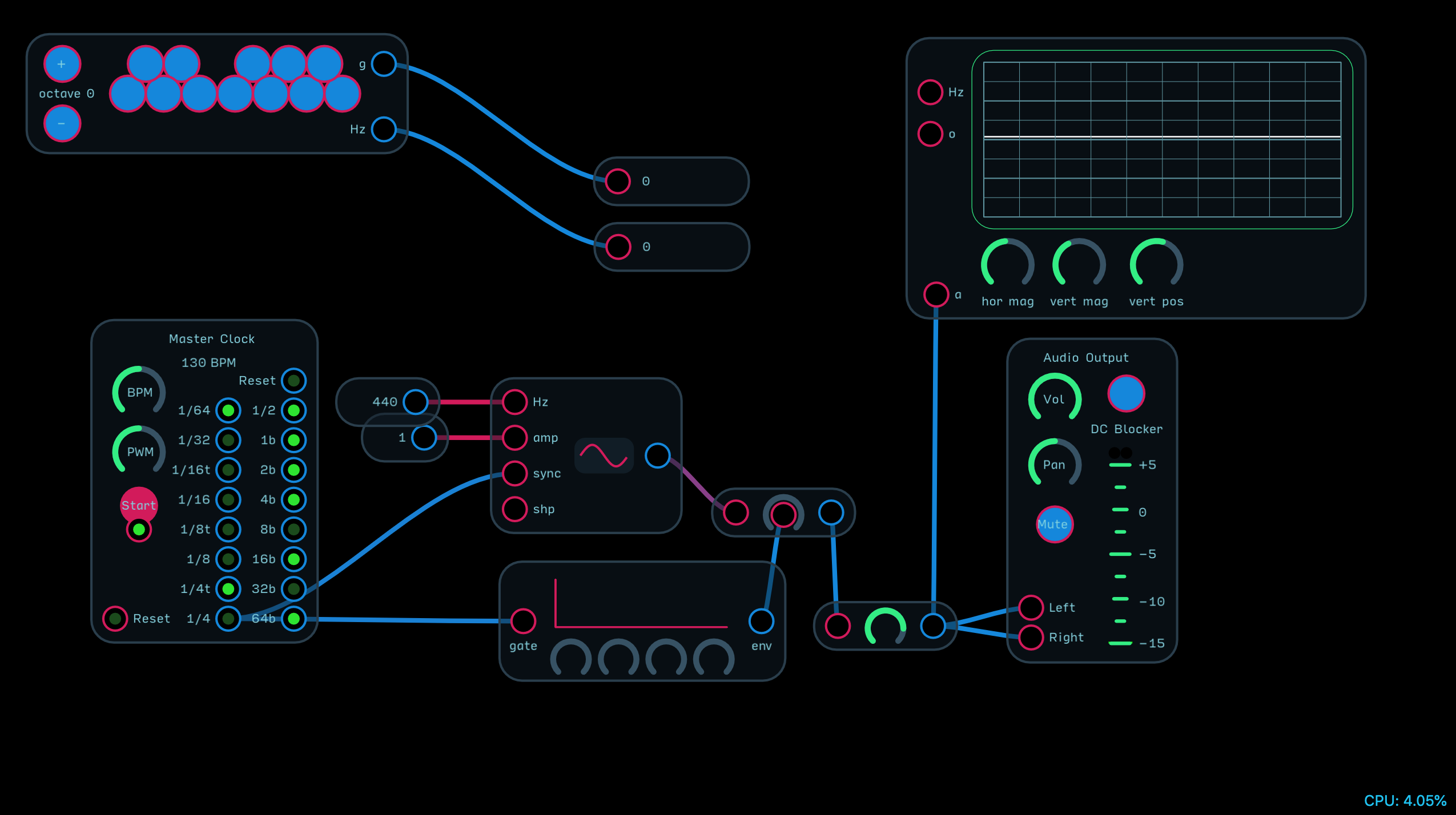
You don’t have the envelope set up to let any sound through. You need to adjust the attack and decay settings higher. If you set them to the lowest settings, it will still create an instantaneous little pulse. If you want to stop the sound, you need to interrupt the gate going to the envelope instead of turning the envelope’s settings down.
The settings you have mean “attack period rises instantaneously to 0 then decays in 0 seconds back down to 0.” This means you still get a tiny click from the attack period.
I also noticed you have the oscillator sync connected to the clock. That will cause the oscillator to re-sync at each clock. When the oscillator syncs it resets the phase of the output to 0. This causes an abrupt change to the output waveform. Although sync is sometimes used to after the sound of the output by triggering the sync at audio rates, generally it’s used to ensure that two oscillators are in phase by syncing them both with the same signal.
Okay. So this means that this is the expected behavior, I just don’t understand how ADSR works.
Could you explain:
When attack and decay are set to their min values, shouldn’t I gear a high/pitched sound click? I can hear a high pitched click/sound if I increase the decay a tiny amount (see below). What happens when the decay is set to its min value, which results in hearing the click in the patch I uploaded originally (instead of the high pitched version in the one below)?
Also, what is the reason for the click (in the original patch) not appearing in the scope meter? Is the meter not precise enough to register the click?
This makes sense. When you say “syncing them both with the same signal” that’s still a gate signal correct? If it’s a gate signal wouldn’t the phase be reset to 0 on both oscillators? Or the idea is that the gate signal is only sent once to reset them (not at a frequent regular interval)?
What do I plug into the amp value of the OSC node?
Also is the shape input for modulation (since there is already a button that selects the waveform type)?
Sync is a gate. It resets the oscillator to 0 phase when the sync input goes positive. Because the frequency of Audulus oscillators doesn’t drift, two oscillators at the same frequency will stay in phase once they’re synced. How you use the sync input depends on what you’re trying to achieve.
The amp input on the oscillator node is for amplitude. It’s usually kept between 0 to 1. You can think of it as an internal level node. In your patch you could have connected the ADSR to the amp input rather than using a level node. Some library oscillator modules don”t have a level input and on those that do it’s often labeled e for envelope.
Nodes are the fundamental building blocks of Audulus. Every patch in Audulus is a collection of interconnected nodes. Nodes can’t be opened or edited. Modules are similar to functions in text based programming. The inputs and outputs of a module are analogous to the parameters and returned values of a function. The labels attached to the inputs and outputs are chosen by the module’s creator and don’t affect the module’s operation. Modules can be opened and edited. The library is made up of modules that combine nodes into functional groupings that are similar to the modules in a modular hardware synth. There have been several revisions to the library with more to come. The idea is to give users a pre-built set of components so they’re not forced to create everything from scratch. The signal range conventions we have adopted as well as the names for inputs and outputs have evolved as the Audulus user community has grown but the intent has always been to make it easier to share our work and to help new users get started.
The pulse is too narrow for the scope to pick it up. The scope works by repeatedly sampling the input waveform at slightly less than the input frequency and feeding the result to a waveform display node. It’s definitely a hack. Try a waveform display node or use an external scope and you will see it. With the ADSR set to zeros you are asking for the signal to rise to 1 instantly and instantly fall to 0. This causes a very narrow pulse which causes the click. When you open the decay slightly you allow a longer burst of the oscillator to pass. The interaction of the narrow pulse width with the underlying oscillator output produces the variation in sound.
So basically if the oscillator does not complete a certain amount of wave cycles our ears do not hear it as a pitch? This makes sense. Do you know what the lower limit of cycles or time is for the human ear to perceive something as a pitch? For example, would one cycle at 440Hz be perceived as 440 (in which case the issue with my patch would be that it does not complete even one cycle) or do we need a lot more to hear a pitch (vs a click)?
The amplitude and sync inputs make sense now. Thank you!
What is the purpose of the shape input (in the presence of a shape selection button)?
I think this paragraph should be the first thing that a first time Audulus user sees (with the option to skip out of it). I understand this now. But it took me a moment. The functions analogy is very helpful to people who have experience with non-visual programming.
The shape input alters the waveshape of the square and ramp (saw) oscillator output waveforms. It only applies to the square and ramp and has no effect on the sine or triangle. It changes the pulse width of the square wave and adds additional sub-ramps to the ramp. To see what it’s doing connect an oscillator node running at around 0.5 Hz with an amplitude of 1 to a waveform display, then hook a knob up to the shape input and turn it up and down.
Cool. Thanks. A quick review suggests that at a few ms (between 6.25ms and 12.5ms) many subjects can still tell the difference between 250 Hz and 255.7 Hz. The min perceivable duration varies based on the pitch frequency.
So when the attack rises “instantaneously” and decays “instantaneously” how long do you think the attack + decay combined actually take @biminiroad ? I’m not looking for a precise number… I’m just curious of how roughly how this relates to say 6.25ms.
Yes, I noticed the built in waveform meter could detect it but the scope hack couldn’t.
Thank you for clarifying. I will try this shortly.
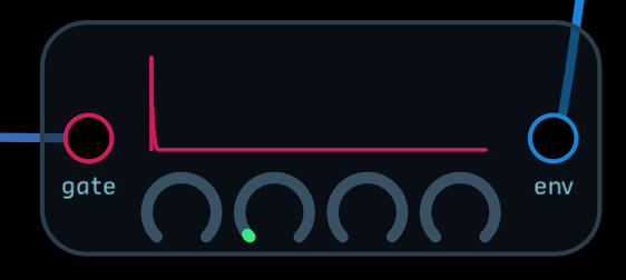
By the way, I noticed that the 2 different scope hack viewers (with and without frequency input) show quite different results (with the same values). The only difference being the frequency input. See screenshot and patch. I assume I should always try to use the one with the frequency input if possible, right (that should be the more accurate one)?
The scope looks like you have some kind of FM or AM/mixing going on? That won’t register correctly - only stable waves will. My suggestion is if you want to see your waves, download Oscilloppoi - a nice cheap scope for Mac - and use Soundflower to route the audio through that app.
I will second @biminiroad’s suggestion. Oscilloppoi is a nice and fairly simple macOS scope and is reasonably priced. It will alway give you a more accurate picture of the output of Audulus
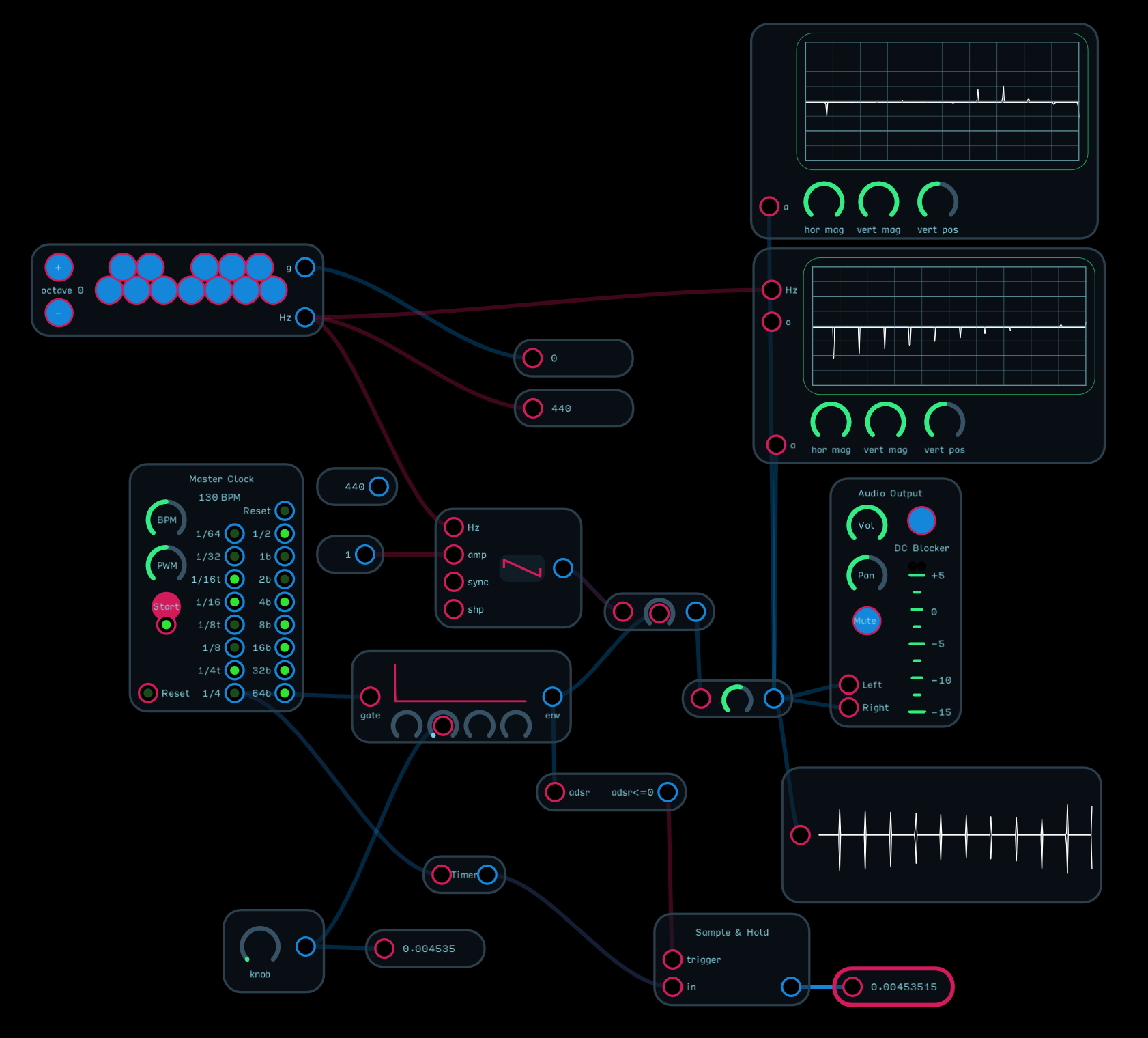
No, I don’t. It’s just the master clock + the osc node + adsr node. Nothing fancy. I uploaded the patch above.
I will. Thanks!
Interesting. I have 2 more questions about this:
How does the decay setting in the ADSR node relate to time? In other words, how many ms is a 0.1 decay value?
How could I make a patch where the duration of my attack (set to value 0) and decay (set to whatever I need to set it to) combined are exact multiple of a full wave cycle (from zerocross to zerocross)? Ex. “a 440Hz sine is exactly 2 full cycles at a decay value of X (and a attack value of 0)” << is it just a matter of specifying the correct X or is this more complicated than I am imagining it to be?
I would like to conduct this experiment partially to see if the click is there due to duration or due to the wave being cut in a strange spot relative to the zerocrossing.
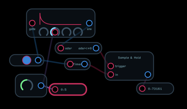
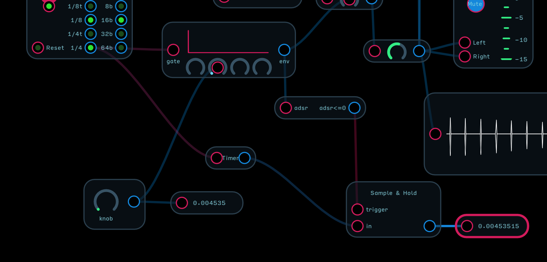
The slopes in the ADSR are linear in nature. Audulus has a Timer node which resets to zero when triggered and counts elapsed time (seconds). Set an ADSR to zero attack, sustain and release and trigger the ADSR and Timer from the same gate. Capture the timer output using a Sample and Hold node by triggering the node when the ADSR output is zero (adsr <= 0). Put a value node on the S&H output and you can measure the time for a given Decay setting. By modulating the Decay with a knob you can also get a reading of the input value. Remember to make sure the gate is high long enough to let the ADSR decay fully
I tried this. I am attaching my patch as well as a screenshot. Could you tell me if my logic (below) makes sense?
440Hz * 2.272727272…ms = 1 second (with rounding)
So I tried setting my decay knob value to 0.004545 to get 2 cycles of a 440Hz frequency per gate/trigger.
Interestingly enough at this level of precision the closest I can get the decay time to 0.004545 is 0.00453515 by setting my decay knob value to 0.004535
The decay value has a resolution and it jumps in steps.