Hey,
I’m making a signal types debugging patch for myself. It includes 4 patches, each related to a signal type. I am uploading the first version of the patch below.
signal-types-alpha-01.audulus (545.3 KB)
The purpose of the patch is for me:
- to have an easy way to get a signal reading that I can easily understand (no matter what module the signal comes from)
- to have an easy reminder of how the different signal types work
It would be great if you could answer the questions I have + share any other feedback on what I am doing.
Please note that I did not know about the livestream on signal types and I am yet to watch it (I will soon)… ![]() Metaphorically speaking: I’m the type of person who tries to build everything without the manual first.
Metaphorically speaking: I’m the type of person who tries to build everything without the manual first. ![]()
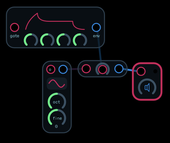
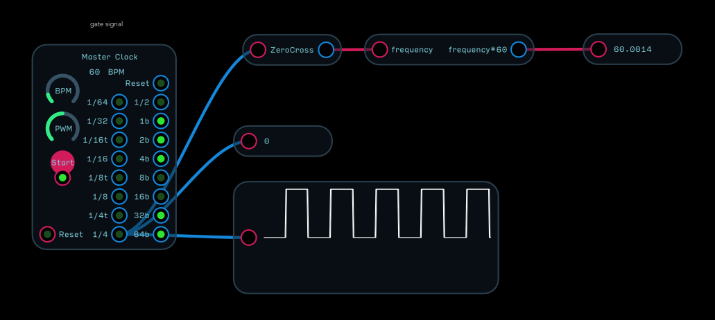
Patch 1: Gate
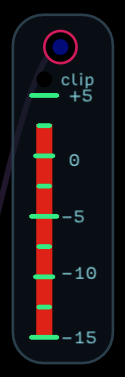
The readouts here are pretty straightforward: BPM, value, waveform meter.
The question I have is: why do I need to output from 1/4 to get the BPM in my zerocross converter? Is the idea that each beat has 4 steps in it? That makes sense to me… I just want to make sure, that’s the case and it’s not an error in the patch/logic. ![]()
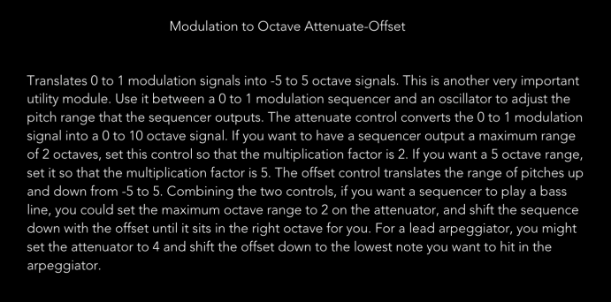
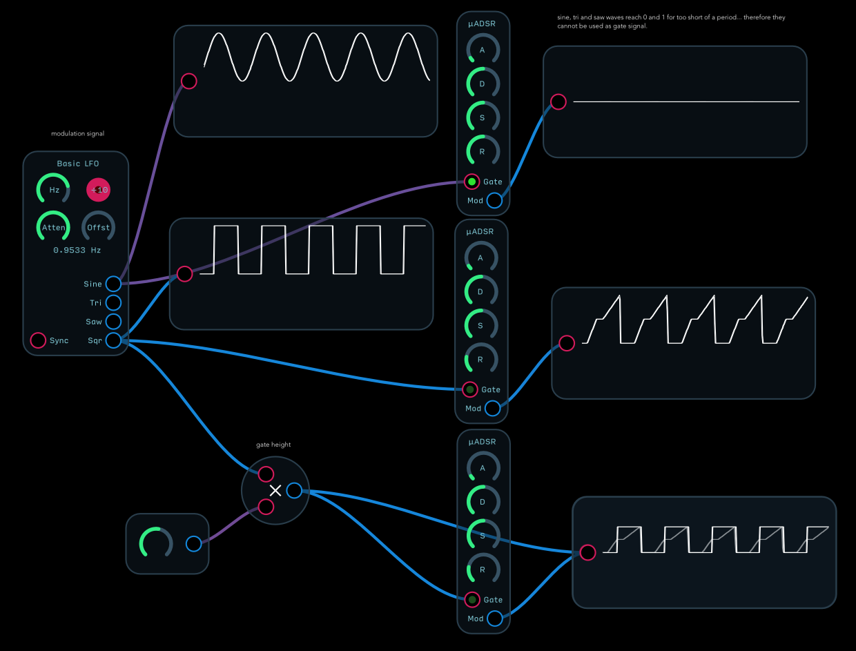
Patch 2: Modulation
This was made by @biminiroad to illustrate what happens when modulation signal goes into a gate input. It’s a great reference IMO. I just added the explanation if why the waveform meter at the top right is a flat line. More details on this here.
No questions for this one. ![]() It’s all clarified in the thread mentioned above.
It’s all clarified in the thread mentioned above.
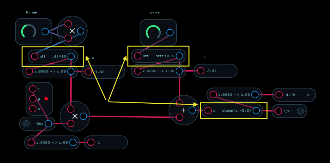
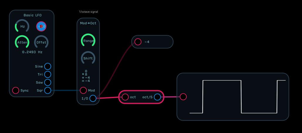
Patch 3: 1/Octave
Here I am simply outputting the signal to a value meter and a waveform meter (normalizing it to fit in the meter first). The question I have is:
Shouldn’t I be able to produce values between -4 and -5 with the Mod->Oct module? -4 is the lowest I can get it to output.
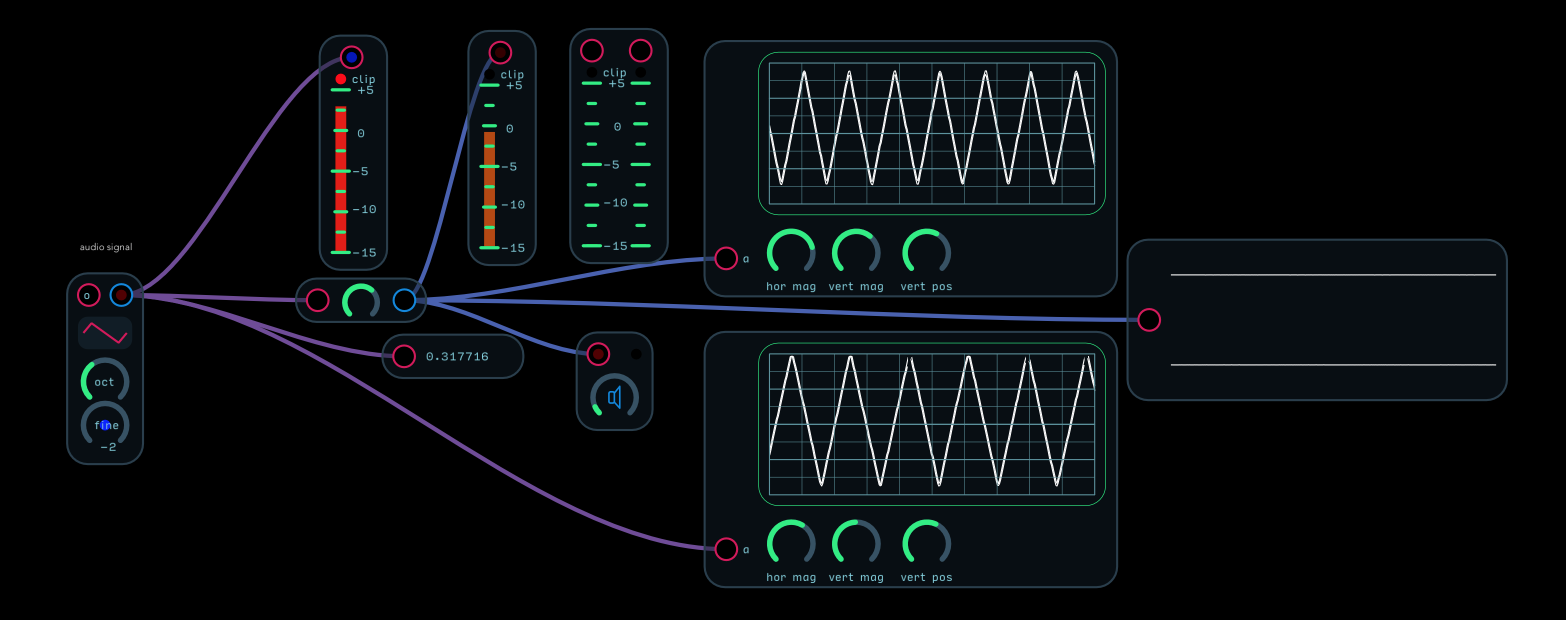
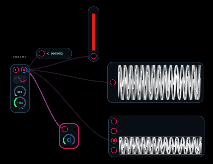
Patch 4: Audio
This needs the most work… Maybe I can share what I would like this part to do and you can tell me how to accomplish it? ![]()
I would like to have 2 meters:
-
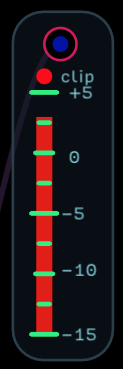
a level/amplitude meter. This is simply to measure if the signal I’m outputting is too hot. What is the best way to do this? Is the meter I’ve thrown in enough? It would be great if I knew what value the ceiling of the meter is?

-
Pitch… I know this is way harder to visualize… and I also have ears for this…
but it would be great if I could visualize pitch within the waveform/oscilloscope meter (without the signal going above/below the waveform meter) in a way that 's visually comprehensible.
A) To stay within the floor/ceiling of the waveform meter I just need a math expression (or a module which converts the signal to -1 to 1 range) correct?
B) As far as it being visually comprehensive I assume I would need some controls for the oscilloscope’s time range? I would basically need to be able to zoom in (the time) to get a useful visual for anything other than a continuous pitch without an envelope.
I feel like someone shared something along these lines (new oscilloscope for Audulus 4 maybe?!) the other day. But I can’t remember the details.
Your input is greatly appreciated!
If I can get all 4 parts to being as useful as I’d like them to be, I promise to record a short video tutorial for beginners like me… Which explains how to use this patch as a learning tool + to debug signals in other patches.