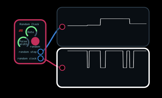
Random Clock
We have a good collection of modules for generating random and quasi-random values of various types but they either generate a continuous stream of values or are clocked in some fashion. The clocks themselves are usually periodic. We do have a random clock in the library but it also has an internal periodic clock with random divisions. I wanted to build a module that has a random time between clock pulses.
I ended up using a random node and timer. The random node produces a random value which is captured by a sample and hold. This, plus 110% of the width of the clock pulse, sets the delay time for the next clock pulse’s leading edge. Adding a bit more than the width of the pulse prevents clock pulses from overlapping. The next clock pulse triggers the sample and hold to obtain the following clock delay etc. Initially I had a fixed length clock pulse with variable timing, but I decided that a random length pulse might be useful in some cases so I added a second random node which varies the pulse width between the minimum value and the value set by the knob.
The unit has two outputs. A clock pulse and random 0-1 step. The step changes values on the leading edge of the pulse and, with a fixed width pulse, is proportional to the delay for the next clock. The pulse width can be adjusted from a minimum of 0.01 to a maximum of 5 seconds. With random enabled, the pulse width will vary between the minimum and the value set by the knob. The maximum delay between pulses is set by the rate knob and varies between a minimum of 1.1 times the pulse width and a maximum of 10 seconds. A low pulse width and low rate will produce widely spaced pulses and a high pulse width and high rate will produce nearly uniform pulses since the delay between pulses will be small relative to the width of the pulse. Seting the rate to maximum and enabling random will produce random width gates separated by 10% of the gate width. All the minimum and maximum values are clearly labeled and can be adjusted if desired. The feedback loops currently use feedback delay nodes which will limit the maximum frequency possible. Using z-1 nodes and changing the default values will allow operation at high audio rates at the cost of significantly higher CPU loads. Because the operation is pretty straightforward, I didn’t feel a separate demo was required but I couldn’t resist. 
I/O
| Input |
Signal Range |
Notes |
| none |
|
|
| Output |
Signal Range |
Notes |
| random clock |
0 to 1 clock |
a randomly timed clock with either a fixed or random pulse width |
| random step |
0 to 1 modulation |
a random length and height step - the height is proportional to the delay time for the next clock |
Controls
| Control |
Function |
Notes |
| Rate |
sets the maximum pulse rate |
1.1 times pulse width to 10 seconds |
| Pulse width |
pulse width |
fixed or random pulse width minimum 0.01 seconds maximum 5 seconds |
| Random |
on (red) random pulse width |
between 0.01 and maximum set by the Pulse Width knob |
Version History
Demos
3 Likes