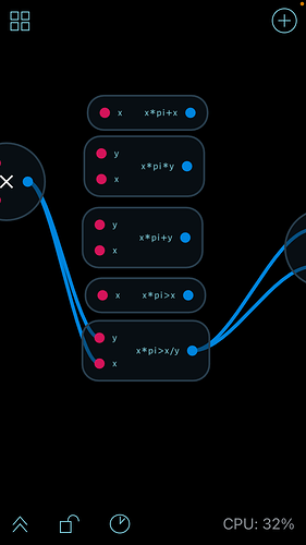
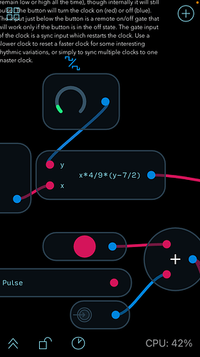
So, really excited by the possibilities here. I’m getting my head around using the exp node and found out it is a great ‘shortcut’ for creating really nice synth patches.(will post pic of patch). Now here’s the thing: would’t it be great to ‘morphe’ between expressions? Is this even possible? I’m trying to figure someting out. Just wondering.
Cool! I found the making connections tutorial really helpfull!
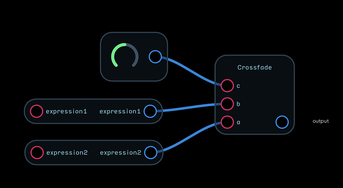
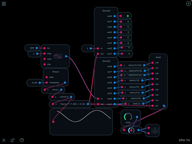
Hey @Stanley! You can also use the Demux/Mux nodes with an LFO by starting with a phasor node output into expression - (sin(x)) and then output that into another expression node - (x/2+0.5), which becomes a sine wave whose output is unipolar 0-1 value, and then multiply the output by expression node - (floor(x*7.98) + 0.01), which will constantly cycle up and then back down the steps of the demux/mux combination. It provides 4x more morph possibilities, through a larger swath of expressions than the cross fade, which is usually my first suggested method for things like this, but @stschoen had already provided that ![]() , so I just dove into exploring, and spent the last 45 minutes building and testing my theory, so I could post with confidence. This is a picture of my method, below. I hope this will also be helpful!
, so I just dove into exploring, and spent the last 45 minutes building and testing my theory, so I could post with confidence. This is a picture of my method, below. I hope this will also be helpful! ![]()
Thanks! I’ll look into that! Might be back with some questions about those expressions. But great.
Hey @Stanley, I have a feeling you are going to have the same questions I had, and if so, you can get the answers about what the expressions mean and why they are used by watching the following videos, from the series, “Know Your Nodes” on YouTube, which was single-handedly organized, demonstrated, and recorded by a very talented member of this forum by the name of @robertsyrett!
KYN part 1 - Making/building custom oscillators of your own in Audulus
KYN part 4 - Understanding and using (even building your own, if you desire) switches in Audulus
Entire Know Your Nodes Playlist - If you have time, give this whole tutorial series a view and bookmark it for review, at a later time. There is an entire university level course study in this series about the math of synthesis and programming modular synthesizers to do what you want them to do, compressed into a ~2 hours long series of videos, and broken down into easily understandable pieces of information that any user on the forum can understand.
I strongly recommend this series, because so much of my baseline understanding of everything I have built and done with A3 (and now Beta-A4) began with this series of videos helping me to gain a foothold in this world. 
Thanks! I am familiar with this series. But now I am watching them more and more. I,ll get the hang of it eventually. And still coming ip with some interesting questions I’ll share later on. Btw. I managed to create a real nice kick with only a clock and a vco! By changing an exp within the clock.
I’m happy to help, and there are many many many others who are also the same way; they just love to help out and make sure everyone feels included. Don’t hesitate to reach out with any other questions you might have come up as your explorations go deeper, and one of us will be happy to answer (or point you to the best resource for the answers).
Additionally, great job with the drum experimentation! It’s so great what a simple clock signal can do to change things, isn’t it? I don’t recall what module I was using it with (maybe the drum kit synth from the Audulus Library?) but the main point of interest in this drum patch I made was the Master Clock module made by @stchoen, and I connected 16th note trigs to the beat of the hihat section, and the 1/4T (or similarly different, being slower and not quite in time trig output) to the tuning or noise knob.
The result of the simple alteration was this super neat, shuffled style drum beat that was way more interesting than the simple 16th notes I had intended to use. That’s a great module for just about everything, btw (in case you don’t have it yet). You should look it up in the forum if it is not saved in your regular rotation, quick access personal library already! 
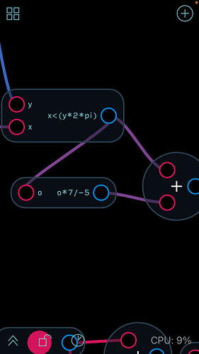
Thanks for all the info! So, yes I’ll try to formulate questions as soon as I come up with ones with stuff I really can’t figure out. Well, the expressions fascinate me enough to really get to use them in a right way. Most of the time I only have my hearing to guide me. That is: no idea what certain stuff (exp) does. But I wondered, if you connect a clock to a vco, it jumps up and down an octave. Why? What makes it do that. And I think I just figured it out by the extra exp. that stchoen showed me. (See picture). Wonder if that clock would affect a sequencer in a different way. Got two free days to get deeper into this amazing maze. So, yes, thank you for your help and questions will be ‘expressed’!
The reason that is happening is due to the (Library Standard) VCO being programmed in such a way that they are reactive to the same type of signals as Eurorack standard equipment, which uses Volt per Octave (1V/o is how you will see it abbreviated in many places), to know which note to output when it is in tune.
So the clock signal is starting with the note which is activated by 0 (which would be 0VDC, if you piped that output through the DAC node and through the output channel matching that of a DC-coupled interface, like the MOTU M4, PreSonus Studio 26c, or the Expert Sleepers ES-8) and I think would be A of the 0VDC octave.
Next, when the clock (provided it is a standard Audulus Library Clock) goes high, the value is 1, so real world would mean that the value is increased to 1VDC by the rise of the clock value, and increasing to (if I am correct about A being the note), A of the next octave in the scale. I hope this is helpful and makes sense. Let me know if I missed any details of what you were asking
For anyone more well versed in the exact translation of V/o standard, please let me know if I am incorrect about the exact note value of 0.000 VDC and then 1.000 VDC. Additionally, I think I recall being told that the sequencer and VCO expected values in our library are offset by a certain whole number (-5, maybe?), and thus, (as I understand it) if we want the note/octave of an Audulus VCO to match the exact note/octave we would get out of 0-1VDC change with a VCO in the real world, it must be offset back by whatever whole number value that it is shifted to work as expected.
Unfortunately there isn’t really a eurorack standard for what frequency a VCO produces when no modulation voltage is applied. The most common pitch seems to be C1 or C2 but it varies between maufacturers. Also many eurorack VCOs have a range switch which allows you to switch octaves.
Because most VCOs have a wide tuning range it’s usually possible to set the zero voltage pitch to any note you desire, so it’s not usually an issue in practice. It’s quite common to tune multiple VCOs to different pitches so that they track together but generate some interesting musical interval such as a fifth or a third. The more important factor is the 1 volt per octave relationship. Regardless of the root pitch, the VCO should change exactly one octave for each volt applied. This allows modules such as sequencers and quantizers from one vendor to work with VCOs from another.
Choosing A440 as the zero reference for the 1 per octave scale in Audulus was arbitrary, but it’s a simple matter to change it if necessary. Setting a standard for Audulus just makes it easier for modules from different users to interoperate. The fundamental VCO node only accepts raw frequency values which are much more difficult to work with.
Thanks. Much usefull inside info here. I feel free to ask away any wuestions I might have. The ‘know your nodes’ videos are good, (That guy is fast though!) and getting into that. I just try to learn as much on my own with help from the tuts in Audulus and so on. And I’ll try to make a question really count! Cheers!
Thanks for jumping in to offer the clarification! I was thinking of when the transpose knob and/or switches are centered/tuned, but then I realized later on that tuning isn’t really a standard, and seems to vary from one performer to another, and in some cases, from song to song, and sort of subjective, depending on who is performing.
IIRC, I heard that Robert Moog was a standard, tuned oscillators guy, and contrarily, Don Buchla believed in using the oscillators as they were when you turned on the synth, or tuning to preference, as it wasn’t so much about the specific notes, but the interesting sounds that you were capable of making with the instrument(s). 
Haha, that guy is fast in those video tutorials – in fact I asked if those tutorials were speeded up, the answer was, hmm, possibly…
To add something that’s probably obvious – when exploring existing modules, the metering nodes (value/waveform/meter) are super helpful to learn what the nodes (for ex., expressions) are outputting.
Sometimes just seeing the min/max output of an expression can lead to a creative way to customize/shape/scale the output, or a simplified expression easier to understand for troubleshooting or whatever.
With shaping in mind, plenty of examples that use the spline or mapper, in combo with expressions, etc. (And I’m using “shaping” as a general term for shaping numerical output, not specific to “waveshaping” suggesting distortion, etc., though that certainly applies, like in @stevo3985 's nice example with the tanh “soft square” expressions above).
Do you mean the Audulus oscillator with Hz input?
Yes. Both the oscillator and the phasor node only accept raw frequency values (Hz). While it would obviously be possible to work in Hertz, there was a consensus that using a scale similar to the one used in Eurorack would make things simpler, particularly for those coming from a modular background. A440 is a convenient zero point since an oscillator without any modulation applied will produce a tone near the middle of the range. Another convention adopted during version 3 was restricting knob and modulation values between 0 and 1. The original V3 knobs will actually allow any range to be set for the knob. This works fine so long as you aren’t trying to share modules but makes “plug and play” difficult. Later V3 knobs and V4 knobs are clamped between 0 and 1. Any scaling should be done internally.
