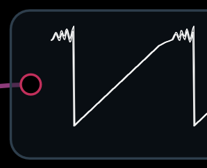
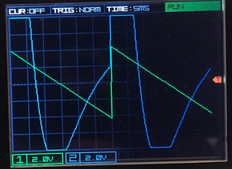
Your first trace looks pretty distorted for a “clean” sound. I have a gristlier schematic so we might be able to model the circuit. What frequency was the trace at?
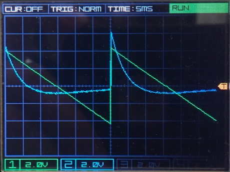
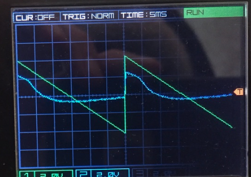
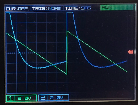
I think the traces are a pretty good start. Where do you have the Bias control set? It looks like the bias control adjusts the bias on the JFET much like the bias control on mine. I can get a somewhat similar trace to your first with the bias turned up some on my JFET model but the falling part of the curve is inverted compared to yours:
I’m not sure I quite understand why your output has such pronounced spike.
I think the curves are probably similar but look inverted in my case. The weird backward scope in Audulus always screws me up. I’ll have to use my “real” scope and how it looks. I’m still puzzled by the amount of distortion in your first trace. I assume the gain of the VCA varies with the bias amount? I intentionally altered the transfer function to make the uJFET stay close to unity gain since I was more interested in the wave shaping aspect, but that could certainly be removed if necessary.
I thought the output looked like a JFET biased way up the curve. The gain increases as the bias increases but it becomes more non-linear as the JFET approaches pinch-off.
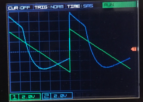
Ok, here is a quickie video. I cut out the sound as it was basically 3 minutes of listening to A 440, which I think we know what that sounds like. Also, sorry that a good chunk of the video is out of focus. It was hard to tell on the small screen while shooting.
In it you can see that the uJFET is actually really close at modeling the parameter that corresponds to “DIRT” on the TG-4. The “BIAS” knob seems to open asymmetrically, filling in the bottom half of the waveform after the top. Also there is a weird glitched out peak that almost looks like resonance that adds some higher harmonics.
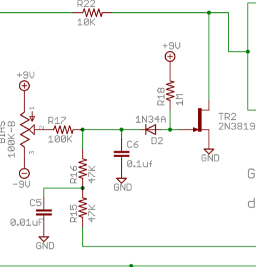
The waveform at 440 Hz as you sweep the bias looks much cleaner than the traces you posted last night. If did the calculations correctly, they were at 33 Hz so the asymmetry may have been due to the low frequency. Unfortunately we don’t have the actual circuit for the TG-4, but in the original Gristleizer the audio signal is fed into the drain leg of the FET from an op-amp through resistor R22 and a bias voltage is applied to the gate. Varying the bias varys the current though the FET which changes the amplitude of the signal at the drain due to the voltage drop across the resistor. When the bias is low, the FET conducts and the output goes to zero. When the bias is high the FET stops conducting and the signal is at max. The FET essentially acts as a voltage controlled resistor (non-linear).
This creates a voltage controlled attenuator. The signal gain is provided by an output op-amp with an adjustable level. The Gristelleizer used this to create a vibrato effect by applying an LFO signal to the gate through R15 and R16.
This explains why my trace was inverted. The uJFET model assumes the input signal is applied to the gate of the FET rather than the drain. This is the more typical configuration for using a FET as a static amplifier. I think I can take the original transfer equation and re-configure it to more closely match this configuration.
The dirt control is pushing the FET into the non-linear portion of its curve. Maybe by varying the gain of the input stage
I think the drive control is probably pushing one of the op-amps into clipping. The hard clip seen on the trace leads me to believe that its probably not the FET itself that’s clipping, but I’ll have do some testing.
Here’s the build notes for the Gristleizer in case you want to look at the rest of the schematic Gristleizer-build-notes-updated-121709.pdf (1.9 MB)
The “glitch” certainly looks like it could be something in the circuit is resonating, but it could be the result of the higher harmonics from the distorted ramp being filtered out.
It could be that I inadvertently didn’t have the BIAS knob turned all the way open either. If you look at the BIAS sweep (around 0:07), the blue trace looks similar to the photos I took yesterday.
From the website:
So this is an educated guess, but there is probably an OTA VCA and the original JFET Gristleizer circuit in some combination. It’s been a while since I watched all the videos on the TG4, but my recollection is that each part had some enhancement made to it. The LFO got a wave shaper, the filter got more state outputs, etc.
I’ve got a bit of a cold at the moment so I’m suffering from some brain fog. (I’m sure old age has nothing to do with it). I’m still trying to figure out exactly what the dirt control is doing. Applying the signal to the drain is not a typical configuration for an amplifier so it might take me a bit to work out what’s going on.
I’m afraid that my clarity of mind regarding circuit diagrams is pretty foggy as well. If I were just to describe it I would say that it’s soft clipping the top of the wave. What I think is interesting is that the rising edge has that resonance and thinking of a way to replicate that is the tricky bit. I think your uJFET is otherwise a great transfer function with BIAS on the uJFET correlating to DIRT.
That’s what the uJFET transfer function does. It clips the top off the waveform as the FET saturates. I wish we had a schematic for the TG-4. I also made a spline based asymmetric distortion module that has a similar transfer curve. You might be able to put a ”wiggle” into the very top of the spline to recreate the glitch.Asymmetric Distorsion Saturator V1.0 demo.audulus (30.7 KB)
It’s pretty hard to work out a schematic from a PCB anyway so please don’t I think we can come up with something useable without it. The spline model might be a reasonable approach. It would be nicer if it had curves but a little extra distortion from the transition between segments probably won’t be noticeable. The JFET transfer function is fairly linear in any case except for the curve between the “linear” and saturation regions.
I’m thinking about possibly using an atan() for the clipping. We could use a clamp but it’s pretty abrupt, although the clip on your traces looks pretty brutal.
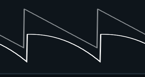
Here’s the waveform from the spline with a “wiggle” at the end. With this approach the wiggle frequency will change with the input frequency.
Not too far off. If the glitch is truly resonance the the frequency of the glitch shouldn’t change with the input frequency. Ableton has a pretty nice spectrum analyzer, you might be able to see the glitch on a sine.
I just checked it out on the oscilloscope an the resonance does seem to have a static frequency, not expanding when I sweep the frequency knob.
I tried to use the spectrum analyzer built in to spot a static spike but was below the threshold. I increased the frequency until the wavelength was approximately the same as the resonant wiggle and I and getting 11.7 Khz
That would seem to indicate that it’s a resonance rather than something introduced as result of the JFET non-linearity. There are enough capacitors and active elements in the circuit that it would be hard to say what’s resonating even if we had the actual schematic. You might be able to use a resonant filter, kick it with a pulse when the signal exceeds some threshold and add the output to the output waveform.
 I think we can come up with something useable without it. The spline model might be a reasonable approach. It would be nicer if it had curves but a little extra distortion from the transition between segments probably won’t be noticeable. The JFET transfer function is fairly linear in any case except for the curve between the “linear” and saturation regions.