@biminiroad: i am pretty conversant in the scaling/rounding stuff. So, I am not mentioning this so much for myself as I know some folks that are daunted by even these seemingly simple things.
Rounding is an interesting thing in that in some situations, it isn’t obvious (unless you have done this a lot or are kinda mathy) when it is useful to floor it or ceiling it.
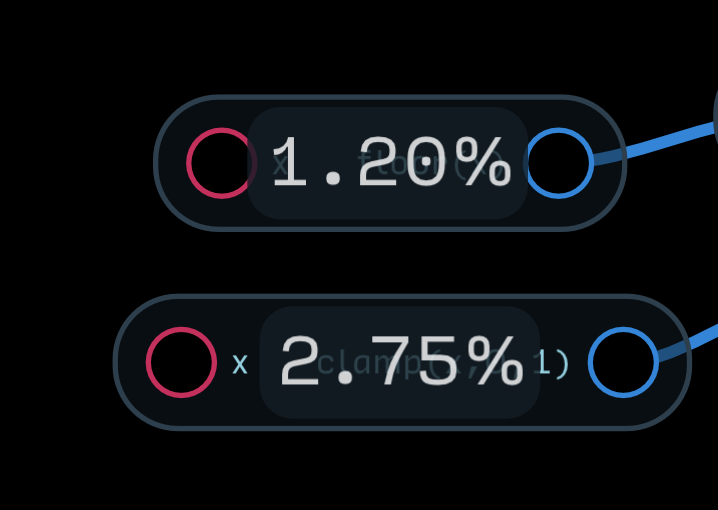
With some knob types (I use them as integer selectors instead of counters because that it is the only way to have the values persist between launches), for instance, I’ve recently realized that I should scale to a larger range than I want and then clamp the knob output to make it less annoying to get the value you want. So, if I want a knob to select 1 through 5, it can be useful to scale the knob’s output for 0 through 6 and then clamp that to 1 through 5 – as it allows you to get 1 and 5 without turning the knob to its extreme.
This is clear. What is the easiest way to debug/measure the clock rate/bpm? My question is: if I have a signal alternating between 0 and 1, what is the easiest way for me to measure how many times it goes between 0 and 1 per minute? Also, is the full cycle (1 then 0) considered one beat or the half is (0 is a beat and 1 is a 2nd beat)?
Got it. Thanks!
I think I will make this tutorial for myself [as a kind of simplistic reminder/debugger for when I’m way deep and need a simple reference point] and post it here, so others can improve it.
I downloaded the examples that go with the docs. I will start going through some of them today.
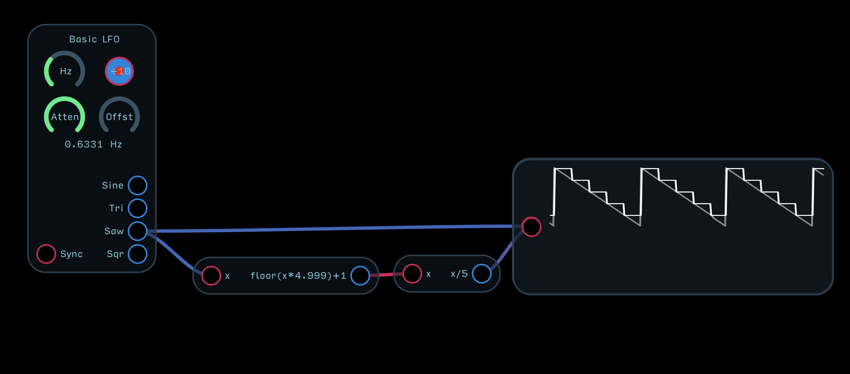
@stschoen showed me recently that you really only have to use floor(x) - check out the example I posted above.
As for building stuff in general and tutorials like this, I plan on making a building manual for Audulus after I get the module library done that illustrates common questions like this
The problem with that is if the knob is turned all the way down, you get 0 - 5 (that is, if it’s a problem for your application). The easiest way to do what you’re describing is do floor(x*range+0.999) - so in your case, floor(x*4+0.999)+1 to get 1-5.
If you want to dial in something with a large number of digits accurately, like 0-999, it helps to split up each place into a separate knob and combine them together (so dial in 100s, then 10s, then 1s, and those 3 numbers get summed together for final number).
@espiegel123’s using a clamp() expression to force the minimum value to 1 and the maximum to 5, so the output of the expression would be 1 to 5. This is probably not as efficient as simply using an offset. I prefer using 0.5 as the offset because it make the transitions even on each end. If you use 0.999 then the expression will output 0 only when the knob is between 0 and 0.001 and the limit 0.001 after the limit -1 is passed. Using 0.5 make the ranges at the low and high end equal.
The case @espiegel123 is describing is for creating integers, so you need to floor it at some point. Doing floor(x*4.999)+1 (which is what I meant to write, not 4+0.999) will make the knob start at 1 and end at 5 with ample space in between.
Great tip. It makes me realize that when I was going through examples before I was sensitive to this issue, I didn’t appreciate why people why people set up floors this way. Elegant solution.
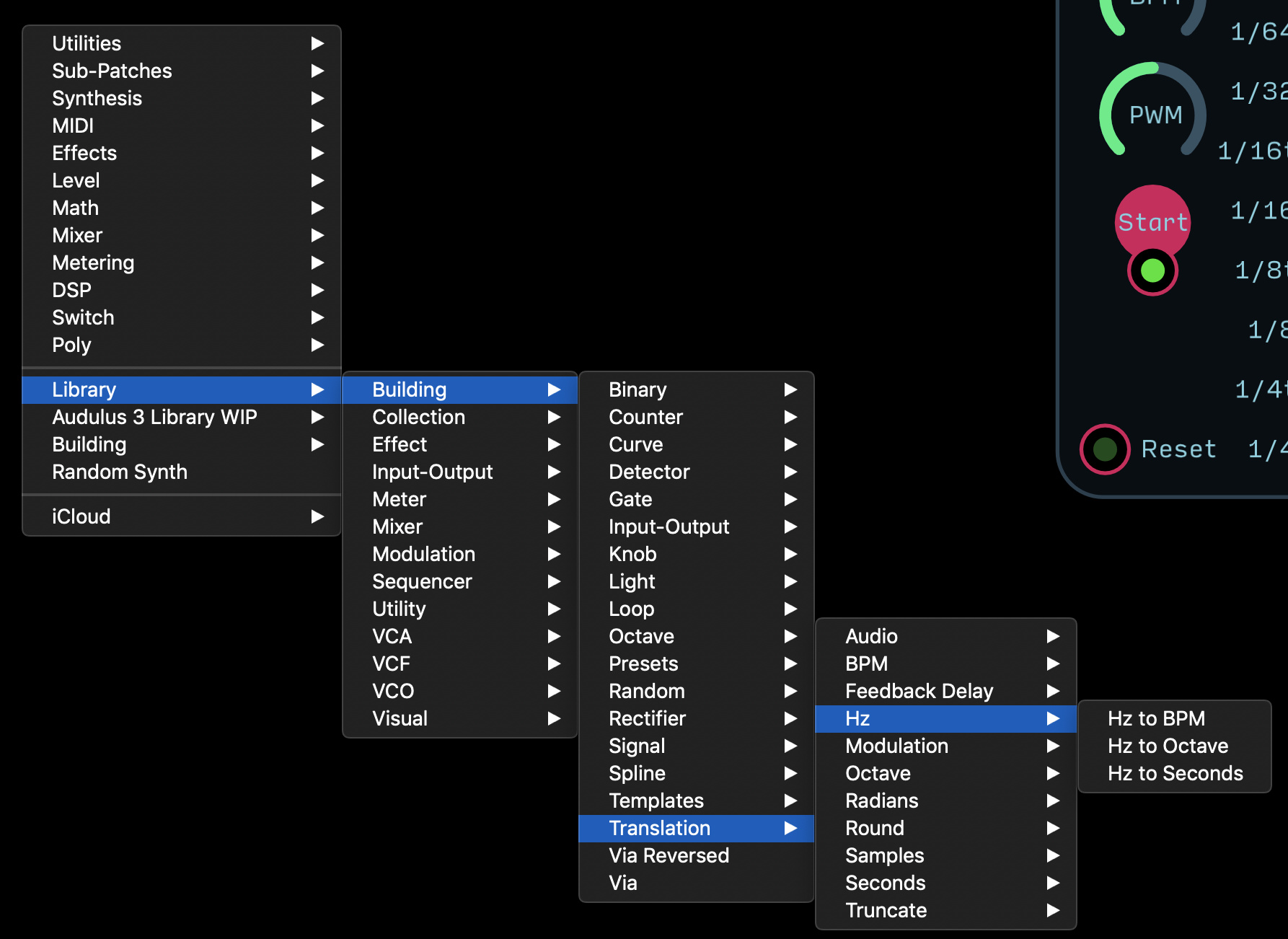
hey, i finally got around to making my reference patch with the 4 kinds of signals. i am playing with the gate/output and i tried what you suggested above [hz to bpm patch] to make a bpm readout.
I was asking a slightly different question. The example you provided is converting the signal. What I am trying to accomplish is convert the signal to a bpm value… like 60 beat/gate cycles per minute signal would show the number 60… 120 beat/gate cycles per minute would show the number 120. I just need a meter to see what I am doing [it’s not meant to connect to to any other input].
what is the best way to accomplish this?
i could probably reverse engineer one of the clocks that has the bpm indicator in the UI. but i assume you know a faster/simpler way.
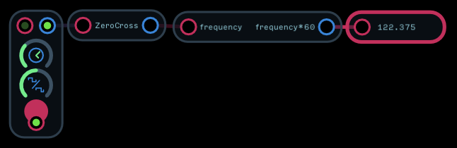
If you know the frequency of the clock it’s easiest to simply convert the number but if for some reason you don’t know the frequency of the clock, you can use a zero crossing detector node to determine the frequency. The node is pretty accurate for signals like clocks that are stable. For any clocks that are generated within Audulus you will always be better off using the actual frequency. In this example, if you open up the clock module you will see that it uses a phasor to create the clock and that the phasor takes a frequency. It would be better to add an output for the frequency to the clock module than to use the zero crossing node.
This is clear. I was able to make one with the ZeroCross. Thank you!
This part is slightly confusing for me. You are basically saying that it’s better to output/measure the frequency (not convert a gate signal to a frequency to output/measure)?
What I’m saying is, rather than measuring the frequency with a zero crossing node, if the clock is being created within Audulus and not coming from outside, you should dig into the clock until you find where the clock frequency is being set and use that number. Most clocks in Audulus are built using the phasor node. Both the phasor node and the oscillator node have a frequency input which determines their frequency, so at the heart of every clock you should be able to find the frequency the clock is set at. Converting a gate to a frequency requires measuring the frequency somehow which takes CPU time and may not always be accurate. It’s better to find the frequency of the thing creating the clock and use it directly
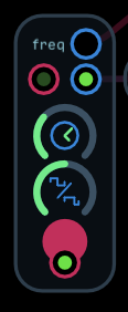
Heres the same clock module with an added frequency output
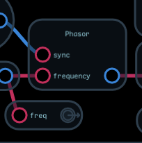
And here’s the inside of the module showing where I added it.
That’s not to say that measuring the frequency is always a bad thing. That why we have the zero crossing and timer nodes. Only that if you can avoid it, you probably should. Sometimes you don’t have a good way to access the original frequency. Signals coming in from an input are a perfect example. If you need to know the frequency of a clock made within Audulus for a module, consider building the clock into the module .