Klee Sequencer
How can a sequence be linear and non-linear at the same time?
The Klee sequencer is built around two 8-bit shift registers. A shift register is a device that passes an input value on to the next of its memory nodes with each clock pulse it receives. Given this cascading bucket-brigade behaviour, the register can function as a delay. In an 8-bit register, the input applied to the first bit appears at the output of the final bit 8 clock pulses later.
More than one bit can, however, be active in the shift register at any particular time, and these values can also be read simultaneously if there is an output for each bit. Information that is entered serially can be read in parallel, i.e. simultaneously, as well as serially.
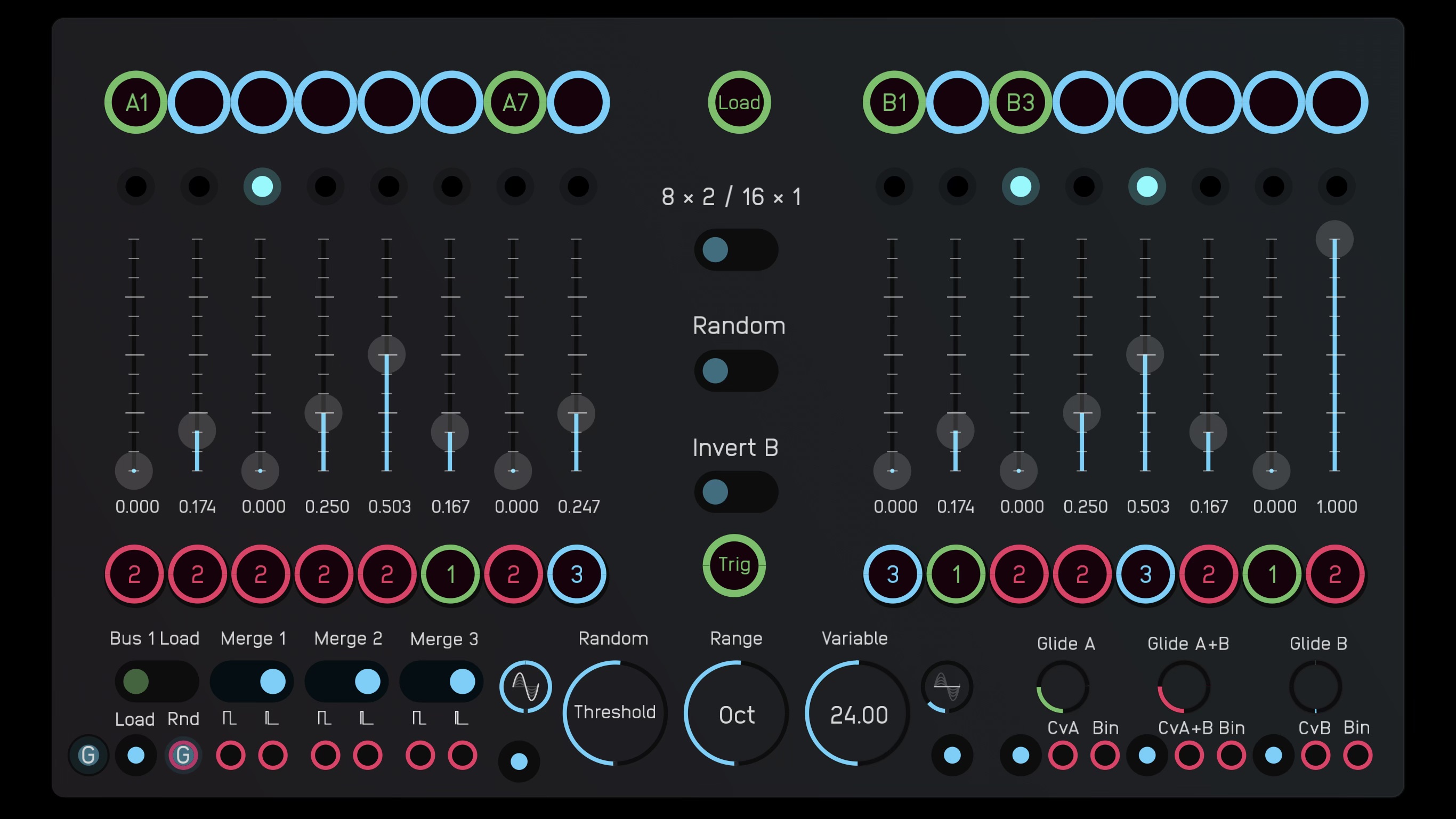
With a single ‘bit’ activated in its shift register(s), the Klee Sequencer can operate as a regular 16-step sequencer, or a set of two 8-step sequencers. The sequencer will step through the levels set on the 16 sliders, either as a single sequence of 16 steps, or two simultaneous sets of 8. The sequence(s) can be reset (by the trigger button or an external gate signal) to start from the first step at any particular point.
With more than one bit active in the shift register(s), the sequencer still advances from one step to the next, as one would expect, but the levels of the sliders corresponding to the active bits are added together. In Moritz Klein’s DIY sequencer, four of these outputs are used as binary numbers to create a range of 16 steps, and Rob Hordijk similarly used three outputs to create a range of 8 in his Rungler circuits.
With the Klee sequencer, all the outputs of the register are simply added together. This can lead to results that are difficult to predict, an aspect that is embraced as a core feature of the sequencer! And since the added values can quickly push the sequence into a generally high range if all the sliders are in the upper end of their ranges and many bits are active simultaneously in a sequence, a range selector makes it possible to scale the range of the sliders between zero and four octaves, bringing the upper limits of the sequence into a more manageable (and hopefully musically useful) range. The ‘regular’ middle setting assigns each slider a range of one octave.
In addition to the ‘Control Voltage’ outputs determined by the positions of the sliders, this version of the sequencer also adds binary outputs for each register: these are 8-bit binary numbers (i.e. covering a range of 256 steps) generated by the active bits in the register, independent of the slider settings. These outputs are a useful additional modulation source that always remains within a range of 0 to 1, no matter how many steps in the register are active.
The sequencer also uses the arrangement of active bits in each register to create gate patterns. Adjacent bits can be merged so as to avoid having a gate pulse on each clock pulse. This can be useful for creating legato ‘slurs’ covering a range of notes. Furthermore, each of the 16 (or 2×8) steps can be assigned to one of three gate buses. Bus 1 can also be used to re-trigger the current sequence, or initiate a sequence that has been lined up via the ‘programming’ switches above each slider. Bus 2 gates are active when neither Gate 1 nor Gate 3 are active, and can also be merged.
Klee Sequencer v1.0.audulus4 (1.1 MB)
Klee Sequencer Demo v1.audulus4 (1.4 MB)