That’s great feedback, will definitely look into refining the knob response for Audulus 4  We’ll also have sliders in A4 too!
2 Likes
Sliders will be great. As I gradually work towards my version of a West Coast Audulus patch and study Todd Barton’s music easel tutorials, I am reminded how the sliders on the Arp Axxe that was my first synth (back in 1974?) were much more friendly than the knobs on a Mini Moog in terms of getting an immediate read on where a patches parameters were at any given moment.
Hopefully, knobs and sliders in Audulus 4 will have color options!
1 Like
They will!
1 Like
Nuther beginner question, what is the best way (I guess in terms of CPU efficiency) of combining outputs of multiple clocks into a single gate stream? Would an expression node be the way to go where and look at its inputs and output 1 if any input is 1 and 0 otherwise?
Related: are spiky pulses better to use as gates in a situation like this than a square wave?
Lastly, what is there a CPU-efficient way to have multiple clock modules in a patch so that they only take up significant CPU when the clock is running? I noticed last night (by turning on the performance monitor in Audulus) that the standard clock seems to take up the same amount of CPU whether it is switched on or off.
Thanks.
Do you want to simply sum a few clocks together and output that as a gate? If so, do (gateOne+gateTwo+gateThree+gateEtc)>0 - it’s basically a multi-input OR gate.
No - a square wave is fine, and the reason the clock is usually set to 50% duty cycle is it’s more useful as a clock/gate combo. Where it needs to for a reset, Audulus just looks at the rising edge, not how long the pulse is.
The way you’d do this is you’d have to remove all of the lights from the outputs. As long as your patch doesn’t have a terminal in a meter node or an audio output, nothing before it will be processed.
1 Like
Thanks. I removed the LEDs from the clock module and rewired the on/off indicator LED to the trigger and that dropped the CPU down. Will the refaced library’s clock have the LEDs removed or rewired in this way?
No - the LEDs are helpful for gates and modulation to understand what’s going on. It’s a compromise CPU wise, but I think from a design perspective it’s worth it. I’m not generally hitting any CPU walls even on my iPhone and even with huge patches I make on my computer that I think won’t be able to run on it.
1 Like
Another question. I am trying to come up with a faux-preset mechanism so that I can can capture the settings of critical knobs and switches and be able to send them back with a click of a button. It looks like Value nodes are read only. Sample and Hold would be interesting for this use but as far as I can tell they don’t hold their value after a file is close.
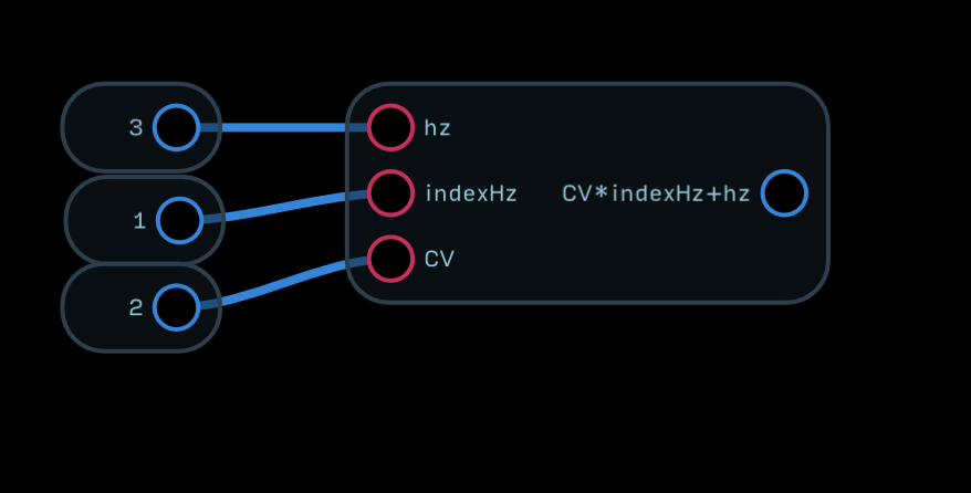
If I wanted to have something like value node that sends out its value when triggered, the only technique I can think of right now is using an expression node with a bogus input. For example, if I want to send 1.55 to somewhere when triggered, I would connect a Trigger to an expression node whose expression is1.55 + (0x). I think the 0x is needed because it seems that an expression node loses its input if there are no variables.
Is there a better way to do this?
You can make an expression node that’s just a value
And you could attach them to Mux nodes, then route the Mux nodes to the inputs you want to use for presets.
Tx. I was aware that you could use an expression node to store a value and that you could send that to a mux, but I guess I was looking for a more elegant lower overhead approach. Where you could send a trigger to the expression node and have it send its value to your desired destination. I was hoping I’d overlooked something.
It would be great if a node were added that let’s you store a value by sending it to one input and then sends it out when a trigger/gate comes in a different input. Sample/Hold does that but is not persistent.
Expression nodes can have multiple inputs, but only one output. The Mux node is pretty low CPU and any alternative you could make with expressions would use more CPU.
The Sample node will be able to do this in Audulus 4 ![]()
1 Like
For my pulsers, it turns out that using spiky pulses is beneficial. It reduces the likelihood that pulses from the two clocks will overlap and be seen as one trigger instead of two…although fat pulses can be fun , too as they result in some different rhythms.
It may seem expensive, but IMO, the Apple Pencil is an indispensable tool for working with Audulus. If you are working with an older iPad or iPhone, then any of the highly recommended styli from Amazon will be a good bet, but nothing can top the Apple Pencil, if that is an option. Just my two cents as a fellow noob ![]()
3 Likes
What is the lightest weight way of delaying a “message”. Is it the delay node with feedback at 0? It seems like Audulus could benefit from a super lightweight node (does it already exist?) that simply passes data through with a user-set delay amount. Ideally it would have an input for the data and an input that used to set the delay amount in milliseconds with no other controls.
1 Like
Right now the delay node is the best way for non-gates. If it’s a gate, you can build a delay by using the incoming gate to trigger a timer node and use a x>delay expression afterwards, like this:
Gate Delay Example.audulus (8.9 KB)
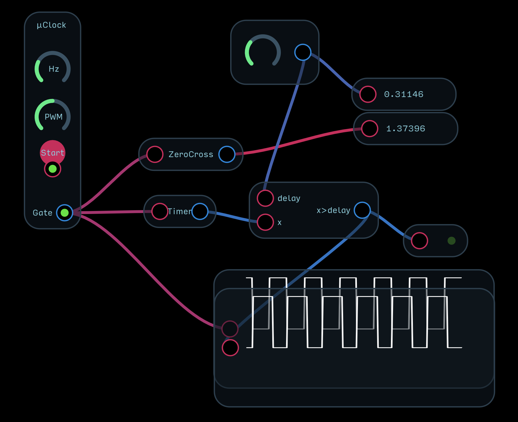
It’s limited though because if the delay exceeds the rate of the incoming clock, it won’t work. Depending on your use this might work though!
This is kind of related to the question above. But has me (embarrassedly as the solution is probably simple) stumped. I have a hack that works but feel like there is probably a more elegant solution that what I am using.
Periodically when I am building things, I find the need to send a single on/off pulse (off programmable duration) in response to an event such as a trigger press or a signal reaching some specified level.
The basic triggered pulse logic that I have works:
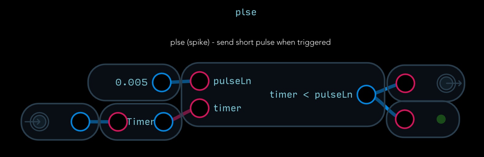
EXCEPT that it also triggers when the app first launchs – since timers are always running
To work around that, I added some (ugly) logic that prevents it from firing unless there has been a legitimate trigger (at some point in the run):
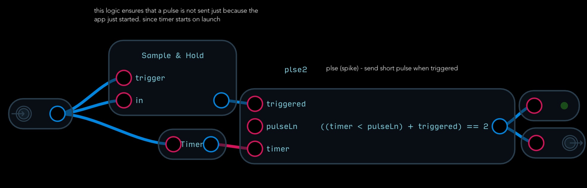
The logic works, but I find my solution inelegant.
What I was trying to figure out (because the general logic would be useful to me for a number of things I am building), was a way so that when the pulse is done to reset the sample/hold to 0 after the pulse is complete.
A related sort of thing is making a two-way toggle switch that sets the routing one way when initially triggered and then toggles back to its original state when an event finishes.
I think this works the way you are describing. The change detector triggers when the timer goes over the length value or when the timer is reset. In order to start the whole process I added the a+b>0 expression as an “or” between in and the timer.
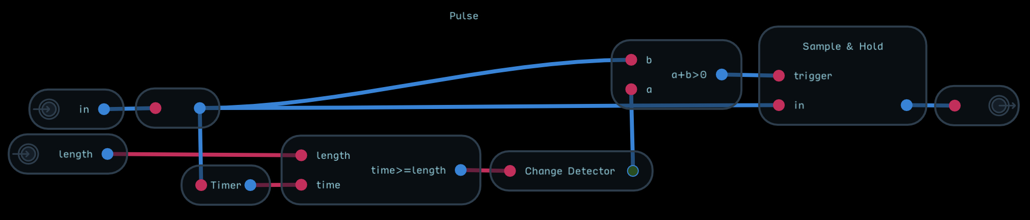
Pulse.audulus (6.6 KB)
2 Likes
Thanks. I’ll take a look at it shortly.
Thanks again. one of my drafts had all the elements that are in Change Detector, but I got the order wrong. Change detector is just what I needed. Now, I need to study it some more.
1 Like