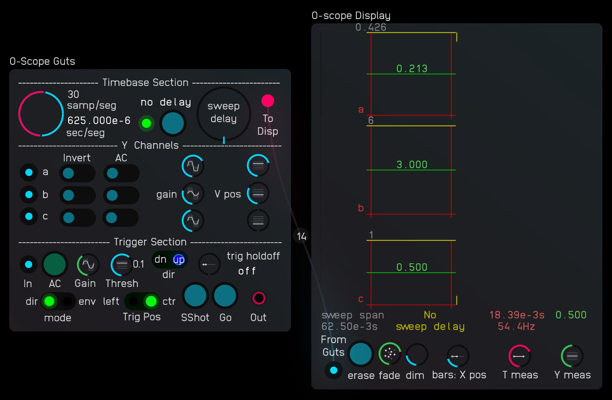
The oscilloscope is three-channel, making use of the scope node’s ability to display the channels of a poly input. A Canvas overlay is used to make measurements. A red vertical unit reference sits on each baseline and a trigger position marker appears at the top and bottom, either at the left or at center, depending on the “Trig Pos” toggle setting.
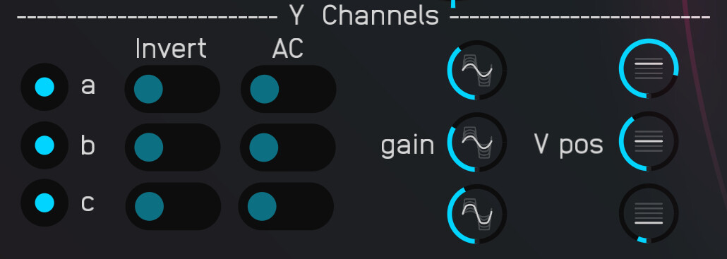
Each channel can be inverted. Each can be direct- or “ac” coupled. Each can be amplified or attenuated. A vertical position control moves each baseline. Signal, gain, and offset for the three channels are all sent as the first 9 channels of a 14-channel poly signal to be sent to the display module.
Setting a gain knob to full counterclockwise for a channel turns off display of the waveform and the canvas elements for that display. It also opens up more vertical space for the remaining channels’ canvas elements. (you’ll probably want to next reposition the baselines of the displayed channels to make best use of the extra space)
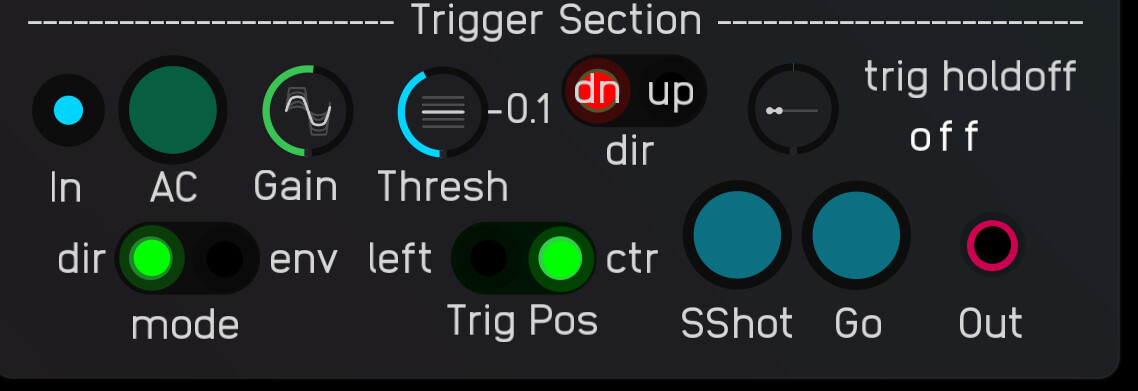
An external trigger is needed to initiate a sweep. The trigger signal can be “ac-coupled” or connected directly. The trigger mode toggle selects whether the direct signal or its envelope should be compared to the threshold set by the threash knob. With the up/down direction switch you can choose to trigger on the leading or trailing edge of the signal.
Triggering can be continuous or it can be set as a single-shot, with the Go button initiating a trace on the next captured trigger, or it can freely run. A “trigger holdoff” control can limit how often a sweep is to be initiated. At bottom, right corner of the trigger section is a trigger output with coincident RGB light. A trigger that initiates a sweep will flash white. A trigger that is skipped during the holdoff time will flash red.
Trigger position is set by the Trig Pos toggle to left or center of display.
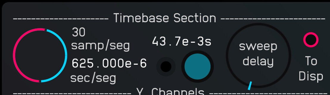
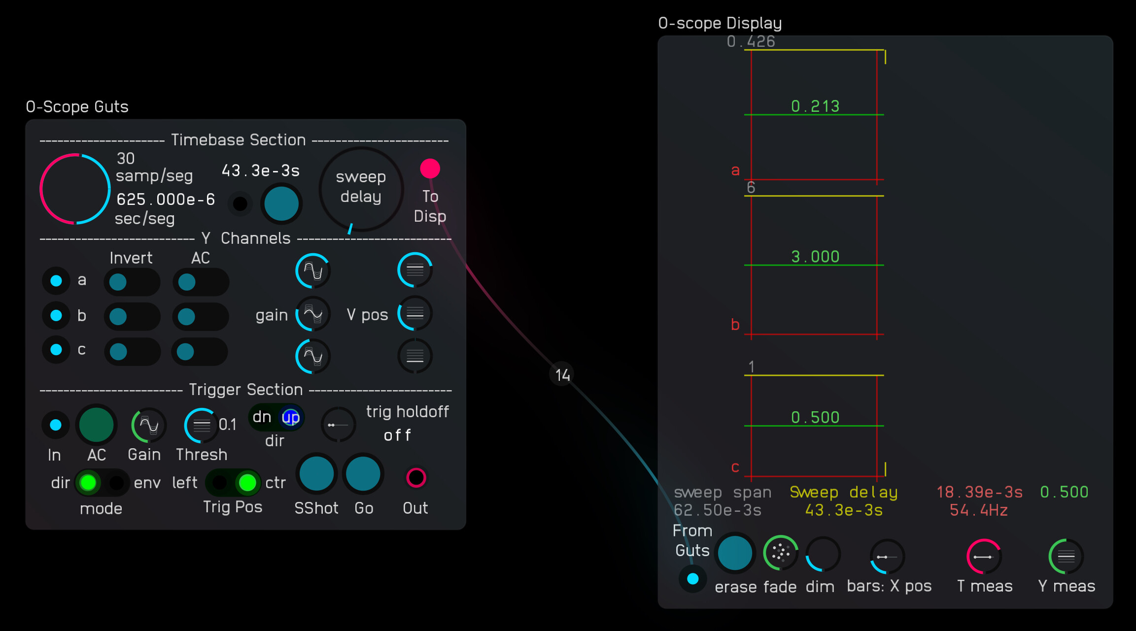
The sweep is divided into 100 segments, with the time base knob setting how many samples will be in a segment, with a minimum of one sample per segment. The sweep can be delayed over a zero to 10s range by turning the “Sweep Delay” knob. This allows you to move the waveform that’s displayed. The sweep delay knob is the “endless” type, with a ratio of one second per turn. You adjust it by spinning about the center or by dragging any edge in the direction you want to go. The delay can be set roughly at a low sweep rate until the feature you’re interested in appears at the (delayed) trigger mark. As you increase sweep rate, the sensitivity to turns to the knob is automatically reduced to allow more precise adjustments. A tap on the button resets delay to zero. The delay value is saved between uses. (Note: this feature uses the “endless knob” module. It’s this delay application that prompted me to create the thing.)
The LED light above the reset button flashes blue with positive changes to the delay value and red to negative changes. It glows green when the delay is zero. (Note that for small changes you won’t see much movement in the knob, but you should see the flashing and the changes in the value.)
The display uses the scope node with an overlaying canvas node. The display can be scaled by resizing the scope node and cavas node. If the scope and canvas nodes are set to match in size and exposed position, they will remain in alignment.
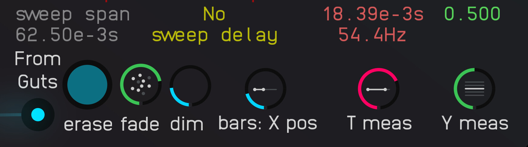
The canvas node is used to create the channel markers (a, b, c), vertical red reference bars with yellow top tick marks, green tick marks that are moved up the red bar following the setting of the Vmeas knob on the display, and upper and lower yellow trigger (or delayed trigger, [T+delay]) marks. The node also displays the associated measurements.
The reference bars follow the setting of the vertical position knobs for the corresponding channels. The reference bars normally display a reference value at the top. As the gain is increased for a channel, the bar will grow onscreen until either the max height for that channel or the top of the canvas is reached, at which point the reference value will take fractional values. As gain is reduced for large signals, the bar will begin to stack, with the value at the yellow line updating by integer amounts to reflect the larger value it represents.
A movable green reference mark follows the setting of the ‘Vmeas’ (voltage measuring) knob, which indicates levels above the baseline. This control scales for each channel, with a to-scale readout in green. Negative-going levels can be measured by flipping that channel’s invert switch.
Setting the ‘tMeas’ (time measuring) knob off-center will split the red reference line in two, allowing time/frequency measurements.
The waveforms displayed will be reset whenever the sweep rate or trigger delay changes, or if a channel’s gain or vertical position changes.
Version History
V9.8 2025-02-12
Oscilloscope scope-node 3-ch v9_8.audulus4 (152.2 KB)
- Added auto display refresh/reset with changes to gain, offset, trigger position, or timebase.
- Added a reset button on the display.
V9.7 2024-05-13
Oscilloscope scope-node 3-ch v9_7.audulus4 (144.4 KB)
- Updated display code for mono-spaced text
- Changed rounding in display module from ‘math.floor’ to ‘string.format’ method to retain number of decimal places for integers (except for the channel max value which sits at the top of each red bar. Those are usually integers.)
V9.5 2024-03-22
Oscilloscope scope-node 3-ch v9_5.audulus4 (134.8 KB)
- Updated fixed-point/engineering displays to fixed width (mono spaced type)
- Added “off” indicators/ special display for delay and trig holdoff readouts.
- Rearranged timebase UI.
V9.4 2024-03-13
Oscilloscope scope-node 3-ch v9_4.audulus4 (124.6 KB)
- Changed sweep delay displays to “fixed/engineering” mode and added digits when the delay reached 1 sec so that you can still see small value changes at large delays. (Fix/eng mode uses fixed point when multiplier is 10^0; Engineering units otherwise.)
- Scaled up the sensitivity of the red/blue flashers with increasing sweep rates. They were going dark when making sweep delay adjustments while zoomed in.
V9 2024-03-11
Oscilloscope scope-node 3-ch v9-3.audulus4 (123.7 KB)
- Added trigger delay wheel and display readout, with trigger position marker.
- Removed trigger position knob and replaced it with a Left/Center toggle.
- Removed sweep direction toggle.
V8
Oscilloscope scope-node 3-ch-231211_01.audulus4 (100.6 KB)
V8 2023-12-11 Increased the options for the time base:
Originally 1, 3, 10, 30, 100, 300, 1000, 3000 samples per segment
now 1, 2, 3, 6, 10, 20, 30, 60, 100, 200, 300, 600, 1000, 2000, 3000 samples per segment
V7
Oscilloscope scope-node 3-ch-231117_01.audulus4 (100.0 KB)
11/17/23
Cosmetic only
V6
Oscilloscope scope-node 3-ch-231114_01.audulus4 (103.9 KB)
11/14/23
V6 2023-11-14
- Make each channel truncate at its local maximum or at top of screen, whichever is closest.
- Got green ref value centered
- Fixed dimming problem with some colors
- Changed threshold for channel off to allow measuring higher values (the value is in an expression node at top left of guts module’s innards)
- Bars grow as channel count drops, down to near canvas_height for one channel.
- Ymeas knob at full CW scales to top amplitude shown for each channel.
V5
Oscilloscope scope-node 3-ch-231109_01.audulus4 (103.1 KB)
11/09/2023
Allows measuring large waveforms (at low gains)
V4
Oscilloscope scope-node 3-ch-231021_01.audulus4 (101.7 KB)
10/21/2023
Ability to turn a channel off
V3
Oscilloscope scope-node 3-ch-231015_01.audulus4 (100.9 KB)
10/15/2023
Small change to indicate the inverted signal with a negative ref value at the top of the bar for the inverted channel.
v2
Oscilloscope scope-node 3-ch-231014_01.audulus4 (100.4 KB)
10/14/2023
V1
Oscilloscope scope-node 3-ch-230912.audulus4 (103.3 KB)
| 9/12/23 | First out there
Demos
Sweep Delay Demo
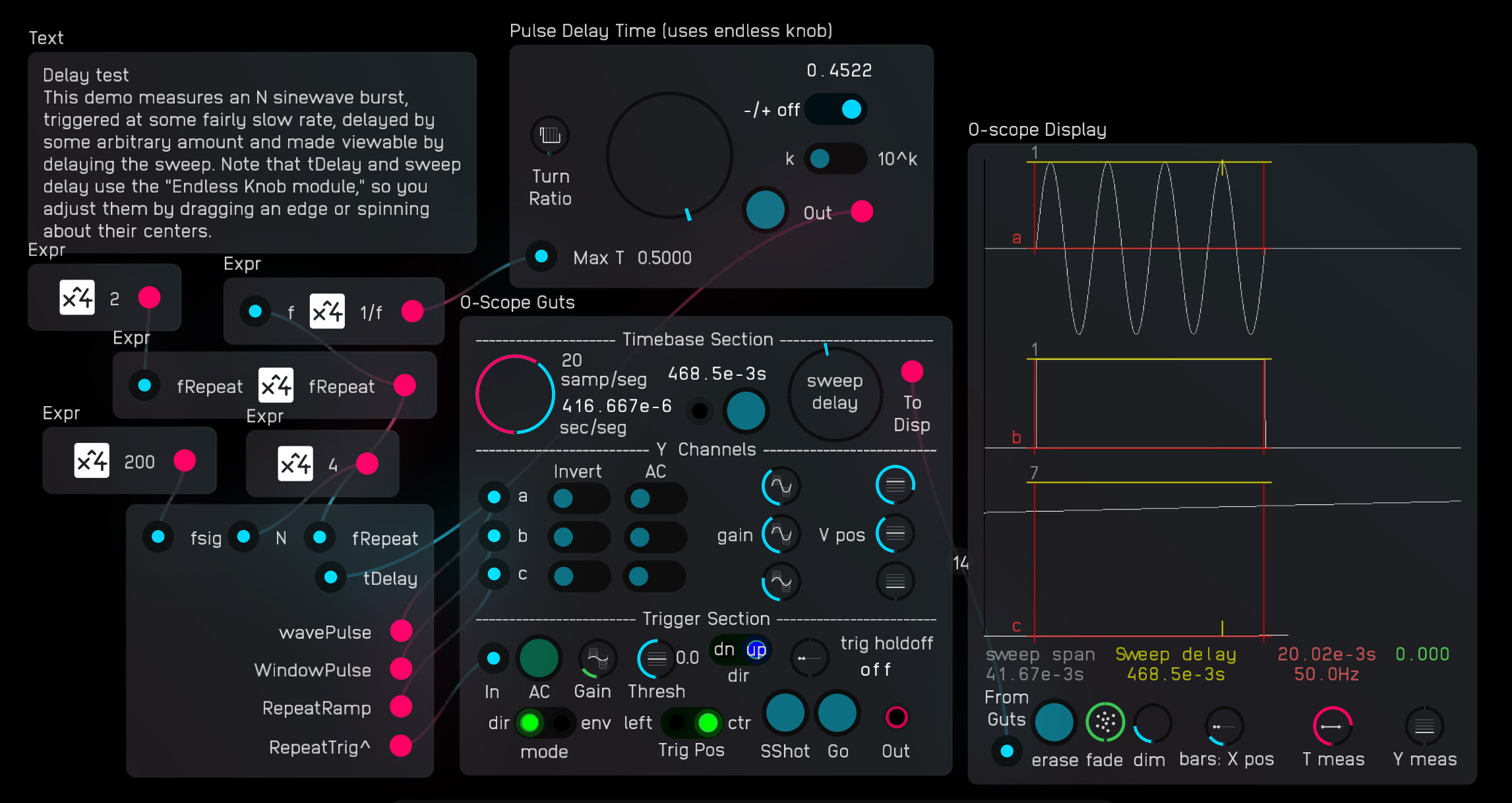
Oscilloscope-sweep-delay-testing-demo.audulus4 (171.4 KB)
Filter Measurement Demo
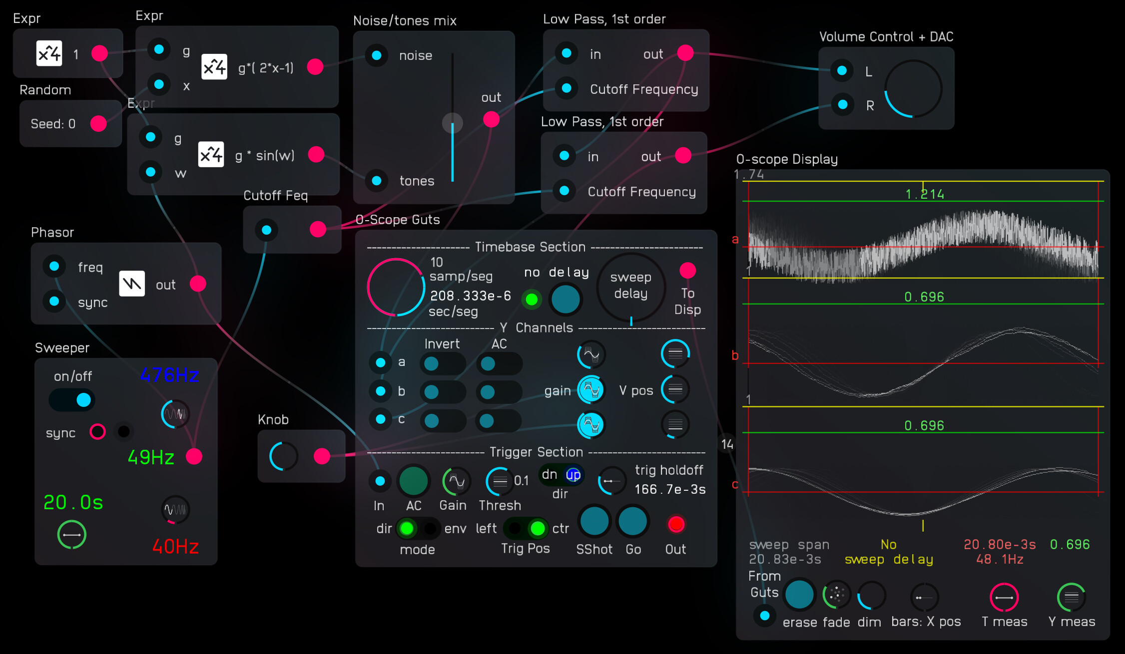
Oscilloscope-filter-testing-demo.audulus4 (178.1 KB)
Teeth Synth Demo

Teeth Synth Demo.audulus4 (257.5 KB)