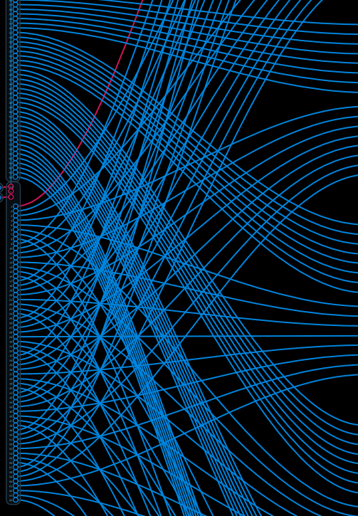
To be fair, I found some good notes on the original sequencer. It helps to watch this video and see the lights cascading from the centre out and back in:
Here are some details I found helpful. According to @biminiroad:
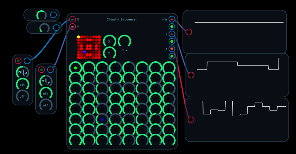
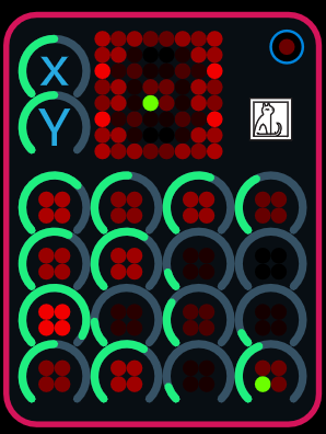
This sequencer uses 0-1 LFOs instead of clocks to drive the sequence step selection. If you use a saw wave input for both sequences, the X sequence is read left to right, top to bottom, and the Y sequence is read top to bottom, left to right. To reverse direction, simply use a reverse saw wave, or even a triangle or sine - or rectified audio! Anything really.
A third sequence is created when X and Y intersect - this is the = output.
The field of values are all scaled 0-1. Best results are obtained when you feed back sequences to the steps themselves.
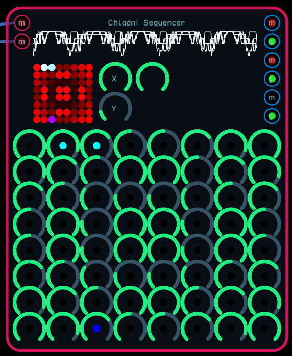
The two controls next to the visualizer are max step controls. The one next to these towards the middle turns the sequences on an off in various combinations.
The difference between a clock-driven sequencer and an LFO-driven one is that a clock-driven sequencer needs all sorts of special count up/down apparatus to move through each steps, especially if you want to do different movements like backwards, ping-pong, pendulum, etc. In this module, you can just send it any kind of modulation signal, like a frequency modulated LFO, that would just be impossible to recreate with a traditional clocked sequencer.
The LFO does not have a negative cycle, since all of the LFOs in the new library are offset to a 0-1 range. Slow the LFO down and attach different shapes and you’ll be able to observe what’s going on.
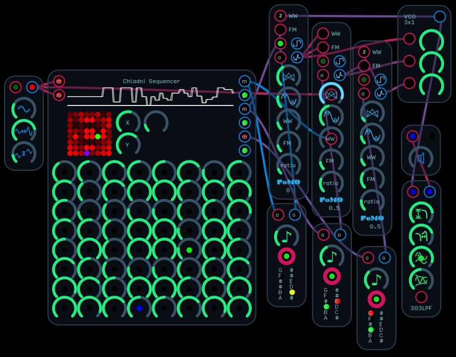
Every time the sequencer moves to a new step, it generates a gate signal. Each step is ranged between 0 and 1. The modules at the m outputs are translating that 0-1 m signal in to an -4 to 4 octave signal, which drives pitch selection.
Also, the sequencer has two outputs - a number that ranges from 0 to 1, and a gate that is either on or off. You have to translate that 0-1 signal into a Hz value and feed it to an oscillator, which the other modules automatically do - you can’t just attach the outputs to a speaker node. In case you don’t want to use the other patches that are there, here is a translator that will take the o signal and turn it into a Hz signal.
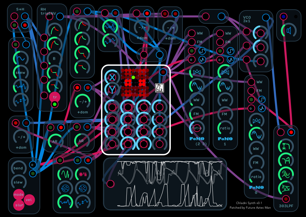
So I am curious about a patch the would cause the lights to behave like a Chladni plate. But also curious if this is possible with @robertsyrett’s take on this design. I guess I would have to try patching the knobs.