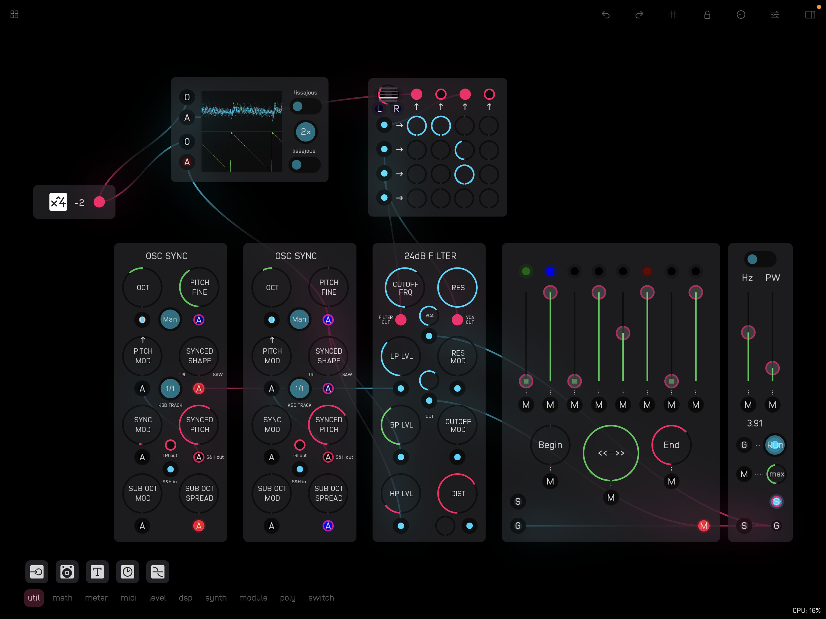
Here’s a take on Rob Hordijk’s 24dB Filter – the last in my series of Audulus versions of his modules.
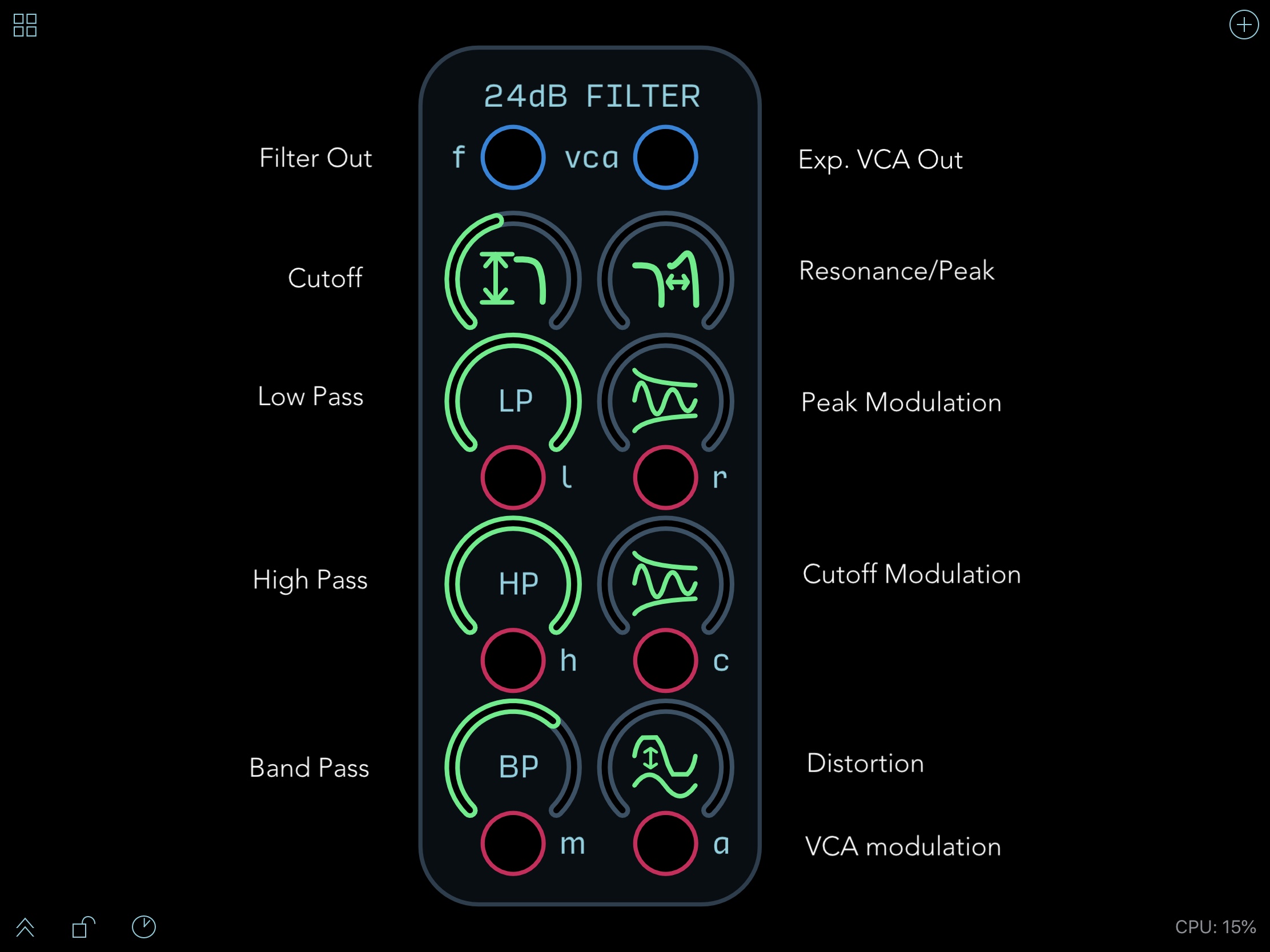
As usual Hordijk gives his own take on the classic Moog 4-pole ladder filter, creating a multimode filter through the addition of high-pass and band-pass inputs all mixed to a single output (rather than a single input with multiple outputs). This arrangement makes it possible to use the filter as a kind of mixer and spectrally cross-fade between the (independent) input signals.
One can also connect the same signal to all of the inputs and use the input controls to shape the curve of the filter.[1] Ideally if the low- and high-pass inputs are set to the same amount (exactly half, for example) they should complement each other and the cutoff frequency (and feedback resonance) should have no effect on the sound.[2] Unfortunately, despite some head-scratching and various attempts, I haven’t managed to get this aspect to work, and one can hear a peak when sweeping though the frequency range. The high-pass with the cutoff frequency all the way to the left does however match the low-pass with the cutoff frequency all the way to the right, and spectrally crossfading between two different signals works well. With the same signal applied to all inputs the cutoff frequency (and potentially resonance) is clearly apparent on the band-pass input and can be used as a kind of equalizer.
Hordijk provides a good explanation of the principles on which the ladder filter is based in his NOVARS tutorial, and with that clear starting point I took the opportunity to dive into the The Art of VA Filter Design by Vadim Zavalishin – the ‘Bible’ of digital filter design as @stscheon puts it – as well as @stscheon’s Introduction to Digital Filters. I found the Introduction useful as an accessible complement to Zavalishin’s in-depth explanations with some good examples of Zavalishin’s diagrams patched in Audulus.
On the basis of @stscheon’s explanations I replaced the LPFs in the 24dB ladder filter with LPFs based on the Audulus LowPass node – and they indeed turn out to be more efficient. Comparing the node-based 1-pole low-pass filter with the patched version from the Audulus Module Library shows that they are almost identical: the node version does however have a slightly stronger attenuation – c. 2–3dB above 10 kHz, or thereabouts. This difference meant that in the 24dB filter the high-pass with the cutoff all the way to the left was slightly brighter than the low-pass with the frequency all the way to the right, and I ended up reimplementing the patched 1-pole LPFs in order to achieve the same brightness. [See above.] (The description in the Audulus docs of the LowPass node having a 12dB rolloff per octave had me confused at first since it matches the 6dB rolloff of the patched 1-pole filter. The 12dB rolloff does however apply to the Filter node.)
1-pole LPF comparison.audulus (42.5 KB)
Zavalishin interestingly describes (in Chapter 4.4) some of the multimode functionality that Hordijk builds on, warning however that:
The multimode functionality of the ladder filter is a rather exotic feature. If you’re looking for the bread-and-butter bandpass, highpass, notch etc. filters, you should first take a look at the multimode 2-pole state-variable filter discussed later in the book.
Exotic or not, Hordijk’s inclusion of independent inputs that simultaneously combine to a single output provides some unique functionality with the ability to spectrally crossfade between them. Although there is a diagram available on The Hordijk Modular Blog I’ve nevertheless been unsure of the details on how to combine the various filter modes. I’m not sure if I’ve solved this in the best way – but, with the exception of the HP and LP inputs perfectly complementing each other, it seems to cover the functionality that Hordijk demonstrates in the video. Regarding the LP/HP asymmetry, my guess is that the four 1-pole LPFs each need to be converted to a HPF to achieve a ‘true’ HP ladder filter as Zavalishin explains in chapter 4.5 of The Art of VA Filter Design. The problem though is then how to maintain the LP signal simultaneously – unless one has a parallel ladder of filters… (which would seem to defeat the point of the design)?
An additional feature of Hordijk’s module is the addition of some subtle tube-like distortion that can help boost the resonant feedback peaks. He favours an all-harmonic distortion rather than one that only boosts the odd harmonics – as is the case with soft clipping and some tube-distortion models, as well as the tanh saturation that Zavalishin suggests in his diagrams. Hordijk generates his distortion through a process of FM feedback and I experimented with achieving something similar building on the techniques that I’d tried out in the Audulus version of his VCA-Shaper and Harmonic Oscillator. In the end I settled on using the JFET VCA in the Audulus library for the subtle all-harmonic distortion that it can provide (the Audulus Tube VCA provides odd harmonic distortion). (I’ve stuck to the standard (clipping) distortion SVG icon, even though I realise that it’s a little misleading in this case.)
The JFET distortion does however introduce a strong fundamental when applied to the high-pass input even though it is effective in boosting the peaks. The introduction of lower frequencies when resonance is applied to the high-pass is however a general problem with the ladder filter design and I haven’t found a satisfactory countermeasure (such as introducing a HP in the feedback loop, as Zavalishin suggests) given the multimode nature of the module. Nevertheless, despite the rough edges in my version, I find it an effective and fun way of blending and shifting between different signals or different spectral areas of the same signal.
RH-RM 24dB Filter.audulus (95.6 KB)
Here’s a basic drone demo with three independent input signals. Change the cutoff frequency to crossfade between them.
RH-RM 24dB Filter Demo.audulus (365.5 KB)
And here’s the same demo with the modulation from the LFOs turned up.
RH-RM 24dB Filter Demo Mod.audulus (365.5 KB)
Here’s another demo with a more rhythmic focus using the VCA output of the filter.
RH-RM 24dB Filter Rhythmic Demo.audulus (432.6 KB)
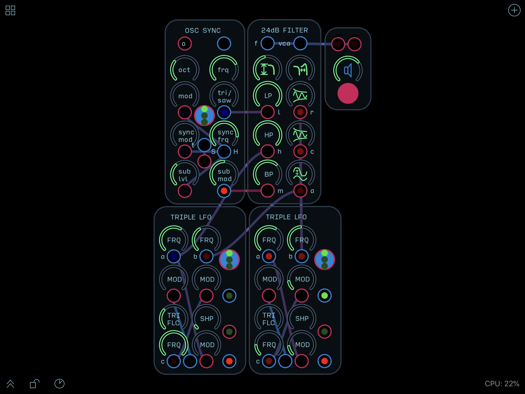
And another along the same lines, exploring a little more of the possibilities of the Triple LFO.
RH-RM 24dB Filter Rhythmic Demo 2.audulus (432.6 KB)

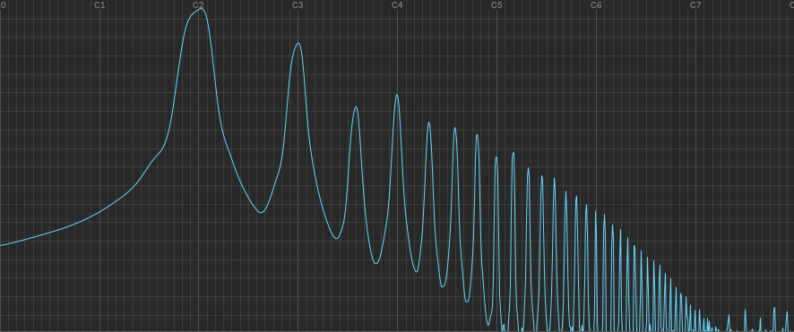
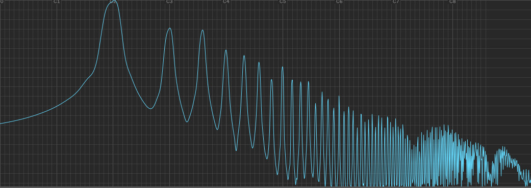
 . Any non-linear transfer function will produce distortion but the exact harmonic content is determined by the nature of the non-linearity. As you so clearly demonstrated, asymmetric transfer curves produce both even and odd order harmonics and symmetric transfer curves suppress the even harmonics. BTW, I love the spectral analysis graphs, what did you use to produce them? The DAW I use (Reaper) has a spectral histogram function, but it’s not this detailed.